© Paul Smith — Alpha & Omega Limited — PlatformClouds.com — Conceptual Engineering Preview — Not Approved for Manufacturing
HERPS-VOL-12-VFD-AFE-SWITCHGEAR-AND-AC-POWER-DISTRIBUTION-REV-D-R2.0.webp

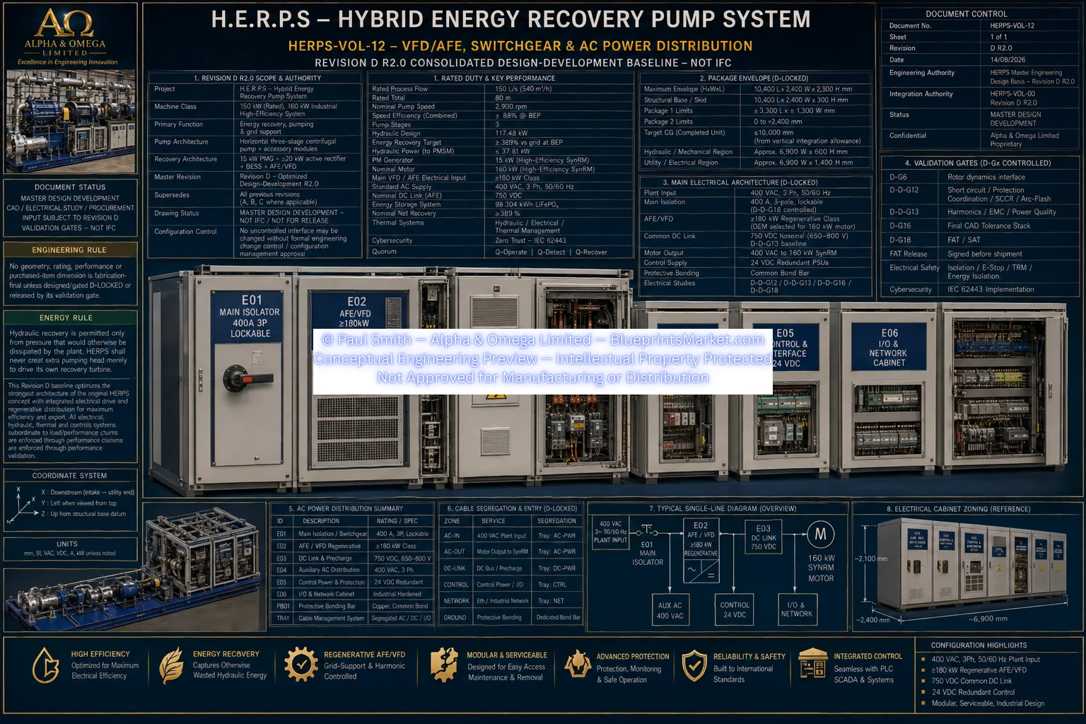
Revision D R2.0 — Electrical Power Conversion, Distribution & Energy Management Architecture
Hybrid Energy Recovery Pump System (H.E.R.P.S)
The H.E.R.P.S Revision D R2.0 electrical architecture integrates the machine's motor-drive power conversion, regenerative energy handling, AC distribution, common DC-link architecture, DC/DC conversion, supercapacitor transient-energy support, battery energy storage, electrical protection, instrumentation and supervisory control into a coordinated plant electrical system.
The electrical architecture is designed around controlled power conversion and managed energy flow. Recovered electrical energy is routed through the appropriate power-electronic and storage subsystems while the main pump drive remains supplied through the defined plant electrical interface.
The regenerative AFE/VFD forms the principal controlled power-conversion interface for the H.E.R.P.S motor-drive system. The Revision D architecture defines a drive class of at least 180 kW and provides controlled bidirectional electrical-energy handling between the drive system and the wider electrical architecture.
The AC electrical subsystem provides the protected plant-side interface for H.E.R.P.S and distributes electrical power to the required machine loads and conversion equipment. Revision D establishes a 400 VAC plant interface together with the associated switchgear, isolation and protection architecture.
Revision D incorporates a common DC-link architecture with a nominal operating voltage of 750 VDC. The DC link provides the central electrical-energy interface between compatible regenerative, conversion and energy-storage subsystems.
Bidirectional DC/DC conversion manages controlled energy transfer between the common DC link and connected storage subsystems. This allows electrical-energy flow to be regulated according to operating state, transient demand, storage condition and supervisory control commands.
The supercapacitor subsystem provides fast transient-energy buffering within the Revision D electrical architecture. Its role is distinct from the longer-duration BESS: the supercapacitor system supports rapid charge and discharge events and assists in stabilizing transient electrical conditions.
Revision D defines a dedicated lithium iron phosphate battery energy-storage subsystem integrated with the wider H.E.R.P.S DC-energy architecture. The BESS provides managed electrical-energy storage while remaining an auxiliary energy-management subsystem rather than the primary source required to sustain pump operation.
| Parameter | Revision D R2.0 |
|---|---|
| Battery Chemistry | LiFePO₄ |
| Configuration | 192S |
| Capacity | 160 Ah |
| Nominal Voltage | 614.4 VDC |
| Nominal Stored Energy | 98.304 kWh |
The BESS is integrated as a managed energy-storage subsystem. H.E.R.P.S is not dependent upon the BESS as its sole source of operating power: the pump architecture is required to remain operable from the grid with the BESS isolated.
The Revision D electrical system coordinates energy flow between the plant AC supply, motor-drive system, regenerative conversion equipment, common DC link and energy-storage subsystems.
Electrical protection is distributed throughout the H.E.R.P.S power architecture so that faults can be detected, isolated and communicated to the supervisory control system without relying upon a single protective layer.
Electrical operating data and subsystem states are integrated into the Revision D control architecture so that the drive, DC link, storage systems, switchgear and protection systems can be monitored as part of the complete H.E.R.P.S machine.
The complete electrical and energy-management architecture is distributed across dedicated Revision D engineering volumes rather than being represented as a single isolated electrical assembly.
This page represents the H.E.R.P.S Revision D R2.0 electrical architecture and supersedes the earlier Revision B electrical-system description previously presented on this URL.
The H.E.R.P.S Electrical Power Generation & Energy Management System forms part of the complete Revision D R2.0 H.E.R.P.S engineering blueprint package available through Blueprints Market.
Contact Blueprints Market for blueprint access, licensing and engineering-package information.
HERPS-VOL-12-VFD-AFE-SWITCHGEAR-AND-AC-POWER-DISTRIBUTION-REV-D-R2.0.webp