
H.E.R.P.S — HYBRID ENERGY RECOVERY PUMP SYSTEM
Thermal Management & Cooling System
Revision D R2.0 engineering design-development architecture for controlled heat removal, coolant circulation, thermal monitoring, equipment protection and package-level heat rejection.
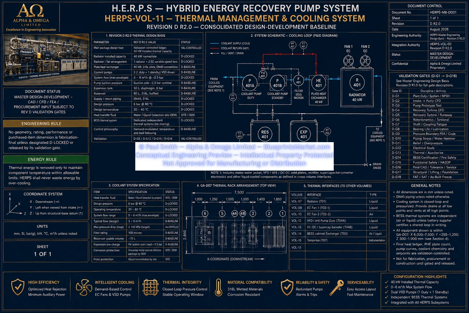
H.E.R.P.S Revision D R2.0 — Thermal Management & Cooling System. Consolidated design-development configuration — not IFC.
Revision D Thermal Management Architecture
The H.E.R.P.S thermal management system is a closed-loop cooling architecture engineered to remove, transport, control and reject thermal losses generated throughout the machine package.
The Revision D R2.0 configuration integrates the primary thermal equipment into the GA-D07 thermal rack while maintaining the required service separation from the electrical cabinets, recovery rotating equipment and other major machine systems.
The main thermal system is based around a maximum demand-controlled coolant-flow envelope of 0–6 m³/h and an installed 40 kW heat rejection capacity.
GA-D07 Thermal Rack
The thermal rack consolidates the radiator, EC fans, plate heat exchanger, circulation pumps, expansion tank, reservoir, filter, three-way temperature-control valve and associated cooling instrumentation into an integrated serviceable assembly.
40 kW Air-Cooled Radiator & Dual EC Fans
The primary heat-rejection assembly uses one 40 kW air-cooled radiator installed in the upper thermal rack together with two controllable EC radiator fans.
Installed Heat Rejection
40 kW nameplate capacity.
Radiator Envelope
1,400 mm W × 900 mm D × 1,100 mm H.
Radiator Fans
Two EC variable-speed fans.
Installation
Upper GA-D07 thermal rack with at least 600 mm free-face clearance and no unacceptable air recirculation.
40 kW 316L Plate Heat Exchanger
The T03 plate heat exchanger provides a controlled thermal-transfer interface within the H.E.R.P.S cooling architecture.
Construction
316L stainless steel plate heat exchanger.
Thermal Duty
40 kW.
Effective Area
3–5 m² design-development baseline.
Connections
DN40.
Cooling-Loop Interface
6 bar closed-loop side.
Process Interface
Where applicable, the selected process side is engineered and certified for the required 25 bar service.
Final plate count, channel configuration, construction method, approach temperature, pressure drop and fouling allowance remain subject to final thermal modelling and vendor selection.
Duty / Standby Cooling Pumps
Two variable-speed circulation pumps provide the main cooling-loop circulation. The system operates with one duty pump and one immediately available standby pump.
Quantity
2 circulation pumps.
Operating Philosophy
1 duty + 1 standby.
Maximum Design Flow
0–6 m³/h.
Operating Pressure
Approximately 2.5 bar at the defined maximum duty basis.
Control
VSD modulation according to thermal and flow demand.
Redundancy
Automatic standby takeover following duty-pump fault or failure to establish required circulation.
Coolant Reservoir, Expansion & Filtration
50 L Expansion Tank
Diaphragm-type expansion tank rated for 6 bar service, providing closed-loop expansion and pressure stabilization.
80 L Reservoir
Baffled 316L stainless steel reservoir providing cooling-loop service volume, deaeration, drainage and continuous level monitoring.
100 Micron Filter
Cooling-loop filtration protects motor, VFD/electronics and other sensitive thermal passages.
DN40 Three-Way Valve
Modulating temperature-control valve providing controlled bypass, mixing or diverting operation according to the finalized P&ID.
DN40 316L Main Cooling Supply & Return
The main H.E.R.P.S cooling circuit uses 316L stainless steel supply and return piping throughout the controlled material schedule.
L-401S Supply
DN40 — OD 48.3 × 3.7 mm — 316L stainless steel — 6 bar.
L-401R Return
DN40 — OD 48.3 × 3.7 mm — 316L stainless steel — 6 bar.
L-402 Fill / Vent
DN20 — OD 26.9 × 2.6 mm — 316L stainless steel — 6 bar.
Total Loop Flow
0–6 m³/h maximum demand-controlled flow.
Routing preserves electrical cabinet access, motor removal, PMG airflow and recovery-turbine service paths while incorporating high-point venting and low-point drainage where required.
Thermal Instrumentation & Monitoring
The thermal-management system incorporates continuous flow, temperature, pressure and coolant-level monitoring to support closed-loop control, equipment protection, diagnostics and commissioning.
FT-401 Flow Meter
0–10 m³/h main cooling-supply measurement.
Temperature Monitoring
Six Pt100 measurement channels covering motor coolant inlet/outlet, VFD/electronics loop, radiator inlet/outlet and ambient temperature.
Pressure Monitoring
Two 0–6 bar-class pressure sensors for supply/return pressure and cooling-loop diagnostic functions.
LT-401
Continuous 0–100% coolant-level measurement within the 80 L reservoir.
Motor, VFD & Power-Electronics Cooling
The main cooling architecture interfaces with the 150 kW horizontal SynRM closed-loop water jacket and provides thermal interfaces for the 160 kW AFE/VFD and other power-electronic equipment where liquid cooling is selected.
Equipment-specific coolant flow, allowable inlet temperature, cold-plate pressure drop and other purchased-equipment limits remain controlled by the applicable OEM thermal data and final heat-balance validation.
The 15 kW PMG remains air cooled under the Revision D architecture and is not treated as a permanently assigned main-loop liquid cooling load.
Independent BESS Thermal Management
H.E.R.P.S incorporates two independent battery-cabinet thermal systems — one for BESS Cabinet A and one for BESS Cabinet B.
These cabinet thermal systems remain separate from the main H.E.R.P.S liquid-cooling loop unless the selected battery supplier explicitly certifies a shared liquid-cooling architecture.
Final battery thermal construction, temperature limits, condensation management, fire interaction and emergency thermal response remain controlled by the battery supplier and the applicable H.E.R.P.S BESS engineering volume.
Thermal Control & Equipment Protection
The EC radiator fans, duty/standby circulation pumps and DN40 three-way valve operate together as the principal active temperature-regulation devices.
Cooling demand is modulated according to equipment thermal requirements. The control architecture monitors coolant flow, temperature, pressure, reservoir level, pump operation and fan status and coordinates alarms, standby-pump takeover and equipment-protection actions.
Final alarm and trip thresholds are established from OEM equipment limits, the validated thermal balance, hydraulic calculations, controls review and commissioning data rather than unsupported assumed values.
Real-World Installation & Commissioning
Revision D defines an installation sequence covering thermal-rack fabrication, radiator and fan installation, PHE and pump installation, reservoir and expansion equipment, DN40 pipework, instrumentation, motor and electronics cooling connections, controls wiring, flushing, pressure testing, filling, venting, commissioning and worst-case heat-rejection verification.
The completed cooling loop is required to undergo controlled flushing and cleanliness verification before final connection to sensitive cooling passages. Pressure and leak testing must remain within the ratings of the lowest-rated installed component.
Final thermal acceptance includes verification of coolant circulation, temperature regulation, duty/standby pump operation, fan modulation, heat rejection, alarms, trips and independent BESS thermal-system interfaces.
Engineering Design Status
The H.E.R.P.S Thermal Management & Cooling System is defined under Revision D R2.0 as a consolidated design-development baseline.
Final coolant chemistry, project ambient and altitude conditions, radiator and fan performance curves, PHE configuration, hydraulic pressure-drop and NPSH calculations, purchased pump and valve dimensions, branch balancing, converter heat-loss data, BESS supplier thermal construction and final alarm/trip settings remain subject to the applicable validation, OEM, site and design-freeze gates.