Rated System Flow
150 L/s nominal system flow through the principal H.E.R.P.S hydraulic architecture.

H.E.R.P.S — HYBRID ENERGY RECOVERY PUMP SYSTEM
Revision D — R2.0
The H.E.R.P.S main hydraulic flow-control architecture manages the combined pump discharge through the DN300 common discharge header and provides two downstream operating paths: the DN300 direct pressure-control path and the DN300 recovery path. The direct path remains available for normal pumping operation without requiring turbine energy recovery, while the recovery path provides the hydraulic interface to the turbine-generator recovery subsystem.
The Revision D configuration integrates discharge isolation, non-slam check protection, main-flow measurement, modulating pressure and flow control, independent mechanical pressure relief, recovery split and rejoin functions, air release, drainage, instrumentation and the DN100 recovery trim/bypass interface within the defined main-water pressure boundary.
150 L/s nominal system flow through the principal H.E.R.P.S hydraulic architecture.
25 bar design-pressure basis for the principal water-side piping and associated hydraulic equipment within the defined Revision D system boundary.
DN300 common discharge header receiving the combined hydraulic output of the operating pump arrangement.
DN300 direct process-flow path providing an always-available hydraulic route capable of maintaining safe pumping operation independently of turbine energy recovery.
DN300 recovery branch providing the hydraulic interface from the common discharge system to the H.E.R.P.S turbine-generator recovery subsystem before downstream rejoin.
DN100 L-D302 recovery trim/bypass interface incorporated into the recovery-side hydraulic architecture.
Main discharge isolation function used to establish controlled hydraulic isolation of the associated discharge section.
Non-slam check-valve function protecting the discharge system against undesirable reverse flow and reducing damaging transient behaviour during changing operating conditions.
Modulating control-valve function governing the DN300 direct pressure-control path and supporting controlled hydraulic operation across the required system operating envelope.
Independent mechanical pressure-relief protection for the main hydraulic system. Final certified relief sizing and set-point requirements remain subject to the applicable engineering validation and design-freeze process.
Primary flow-measurement function used for operating measurement, control-system feedback, commissioning and hydraulic performance verification.
Controlled drainage and high-point air-release provisions support filling, venting, draining, commissioning, maintenance and safe hydraulic operation.
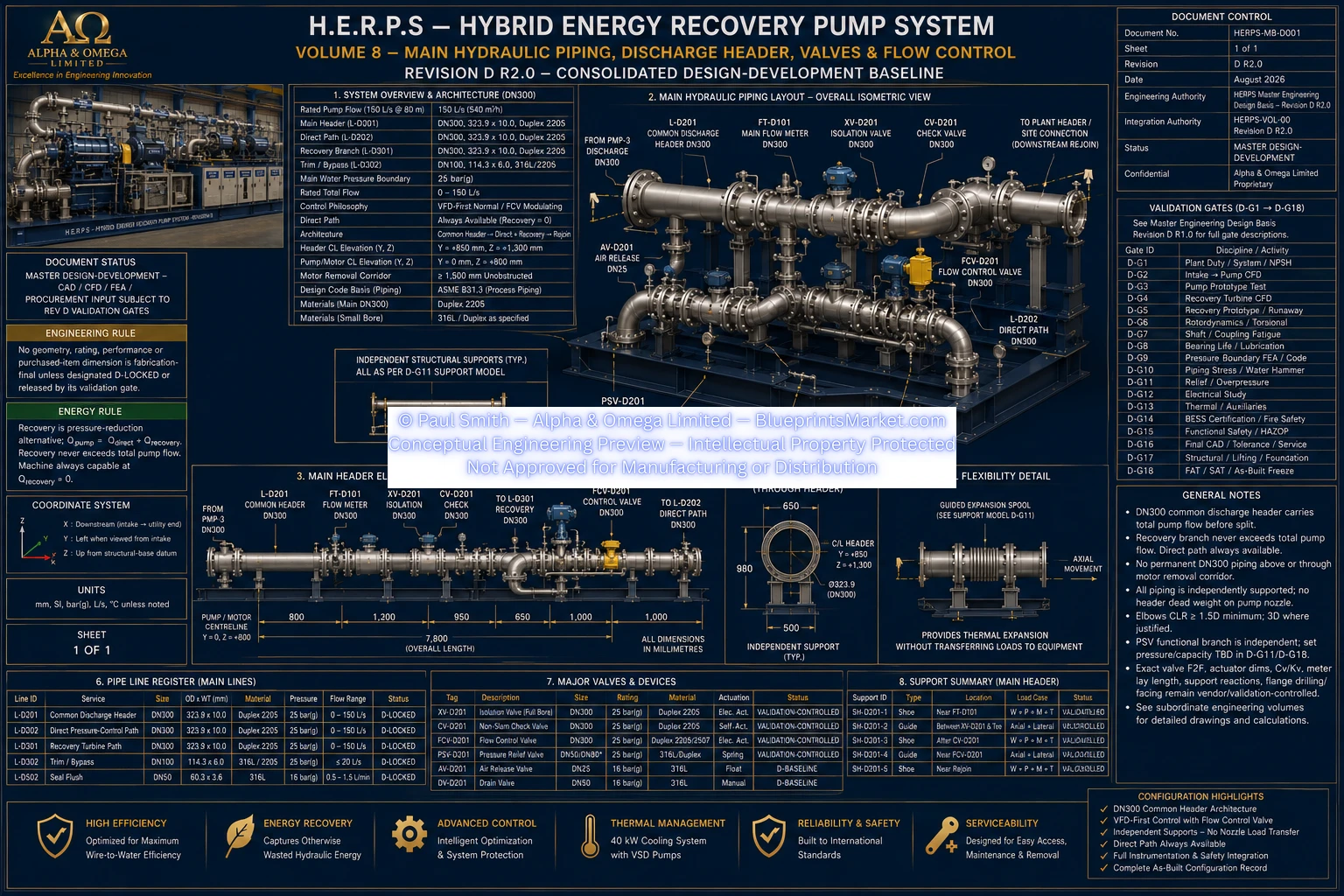
HERPS-VOL-08-MAIN-HYDRAULIC-PIPING-DISCHARGE-HEADER-VALVES-AND-FLOW-CONTROL-REV-D-R2.0.webp
Revision D establishes the direct hydraulic path as a fundamental process-flow route rather than making operation dependent upon the energy-recovery turbine. Water leaving the common DN300 discharge header can therefore be controlled through the DN300 direct path while the recovery branch is unavailable, isolated, under maintenance, commissioning, or otherwise not being used for energy recovery.
The recovery branch operates as a parallel hydraulic route from the common discharge architecture into the turbine-generator recovery subsystem. The hydraulic streams are subsequently managed through the defined downstream system architecture so that energy recovery remains subordinate to safe pump and process operation.
This arrangement separates the essential pumping function from the optional recovery function and provides the control, isolation, protection and instrumentation interfaces required for commissioning, operating-state transitions and controlled maintenance.
Final hydraulic release requires validation of the complete installed flow-control system, including system resistance, operating pressure, valve authority, transient response, water-hammer behaviour, relief protection and the interaction between the direct and recovery paths.
Purchased-valve face-to-face dimensions, flange drilling and facing, actuator envelopes, certified Cv/Kv characteristics and final relief data are controlled through the applicable vendor and engineering validation process rather than being assumed from nominal valve size alone.
FAT, SAT and commissioning activities verify that the installed hydraulic configuration corresponds with the released Revision D arrangement and that measured operating performance satisfies the applicable acceptance requirements before final system acceptance.
This page presents the Revision D R2.0 conceptual engineering architecture of the H.E.R.P.S flow-control, valve and hydraulic routing subsystem. Final manufacturing dimensions, purchased-equipment selections, certified valve characteristics, relief settings, fabrication details and installation requirements remain subject to detailed engineering validation, supplier-certified data and formal design release.