© Paul Smith — Alpha & Omega Limited — PlatformClouds.com —
Conceptual Engineering Preview — Not Approved for Manufacturing
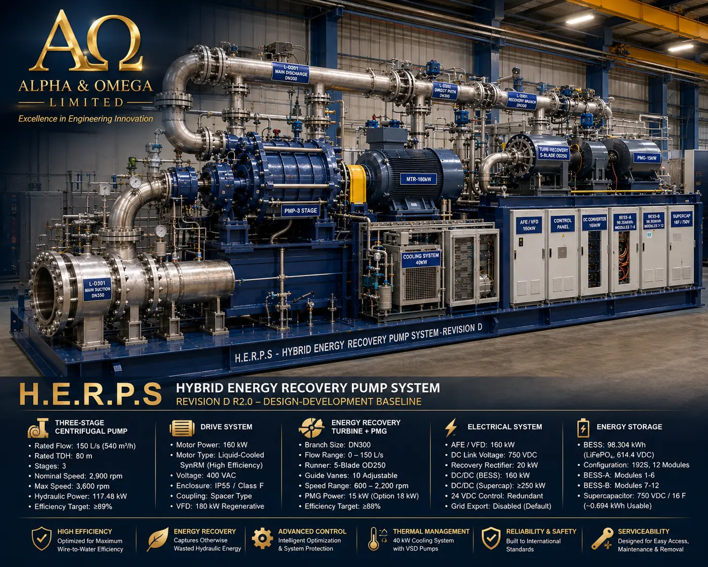
HERPS-3D-COVER.webp

Revision D R2.0 — Industrial Water Pumping • Hydraulic Energy Recovery • Integrated Electrical Energy Management
A coordinated three-stage variable-speed centrifugal pumping platform with a parallel pressure-energy-recovery branch, regenerative electrical architecture, thermal management, energy storage, industrial controls and structural integration.
HERPS-3D-COVER.webp
H.E.R.P.S — the Hybrid Energy Recovery Pump System — is a skid-mounted industrial water-pumping architecture developed around a horizontal three-stage variable-speed centrifugal pump and a controlled parallel hydraulic energy-recovery branch.
The primary function of the machine is pumping. The energy-recovery subsystem is secondary to that duty and is designed to recover energy only where the plant process provides a genuine otherwise-wasted pressure reduction. The recovery architecture therefore supplements the overall energy-management system without replacing the external energy required to drive the primary pump.
Revision D integrates the hydraulic, rotating, electrical, thermal, energy-storage, controls, structural and site-interface disciplines into one coordinated engineering-development platform.
| System Parameter | Revision D R2.0 Public Design Baseline |
|---|---|
| Primary Duty | 150 L/s (540 m³/h) at 80 m TDH |
| Pump Architecture | Horizontal three-stage variable-speed centrifugal pump |
| Nominal Pump Speed | 2,900 rpm |
| Controlled Speed Envelope | Approximately 1,500–3,600 rpm development range |
| Main Drive Architecture | 160 kW-class liquid-cooled synchronous reluctance motor system |
| Main Suction Interface | DN350 |
| Common Discharge Interface | DN300 |
| Direct Hydraulic Path | DN300 |
| Recovery Hydraulic Branch | DN300 |
| Main Water Pressure Boundary | 25 bar(g) design-development basis |
| Common Electrical DC Link | 750 VDC nominal |
| Battery Energy Storage | LiFePO₄ BESS architecture |
| Supercapacitor System | 750 VDC-class transient-energy subsystem |
| Thermal Management | 40 kW installed heat-rejection architecture |
| Control Architecture | PLC / HMI / SCADA with independent hardwired protection |
| Engineering Status | Revision D R2.0 Master Design-Development — Not IFC |
The primary hydraulic machine is a horizontal three-stage centrifugal pump developed around the rated 150 L/s at 80 m TDH operating duty. Variable-speed control allows the pump operating point to be matched to actual process demand rather than relying exclusively on throttling.
Downstream of the main pump, Revision D provides both a direct hydraulic process path and a parallel recovery path.
The direct path remains available for essential pumping operation even when the recovery subsystem is unavailable, isolated, under maintenance or not economically useful. This prevents the primary plant pumping duty from becoming dependent upon the energy-recovery turbine.
The recovery path diverts only the permitted portion of actual pump flow through the turbine where recoverable pressure head genuinely exists.
The governing hydraulic conservation relationship remains:
Qpump = Qdirect + Qrecovery
The recovery subsystem converts otherwise-wasted hydraulic pressure reduction into rotational mechanical energy through a dedicated hydraulic turbine.
The turbine is mechanically coupled to a permanent-magnet generator, allowing genuine recovered hydraulic energy to be converted into controlled electrical energy for the machine's DC energy-management architecture.
Recovery operation remains subordinate to hydraulic process requirements, safe pumping operation and validated available head. Additional pump head is not intentionally created merely to increase electrical recovery.
Revision D uses a high-efficiency synchronous reluctance motor architecture with regenerative AFE/VFD power electronics to provide controlled variable-speed operation of the main pump.
The H.E.R.P.S electrical architecture coordinates the main regenerative drive, recovery generator, active rectification, common DC link, bidirectional conversion, battery storage and transient-energy support within one controlled electrical platform.
Revision D incorporates a dedicated LiFePO₄ BESS arranged across two cabinet zones and interfaced with the common DC system through controlled bidirectional power conversion.
The battery system provides managed stored-energy capability and operates under dedicated battery-management, isolation, monitoring and protection functions. It is not presented as the permanent source of the main pump's operating energy.
A high-power supercapacitor subsystem complements the BESS by handling rapid short-duration charge and discharge events.
This allows transient-energy buffering to be separated from the longer-duration storage duty of the battery system and supports controlled DC-link behaviour during rapidly changing operating conditions.
The Revision D machine incorporates a dedicated thermal-management rack serving the main motor, drive electronics and other defined thermal loads.
H.E.R.P.S uses an integrated automation architecture to coordinate hydraulic operation, motor control, recovery operation, electrical-energy management, thermal systems, alarms, trips and machine diagnostics.
Protective functions are not dependent solely on ordinary supervisory software. Revision D incorporates independent hardwired safety and trip functions alongside PLC-based control.
The mechanical, hydraulic, electrical and thermal systems are coordinated on a common structural base designed to preserve equipment alignment, support operating loads, accommodate lifting and transport requirements and maintain service access around the machine.
Foundation anchoring, grout, structural interfaces, lifting points, equipment supports and final site connection requirements are controlled through the dedicated structural and foundation engineering volumes.
Revision D incorporates service access as part of the package architecture rather than treating maintenance as an afterthought.
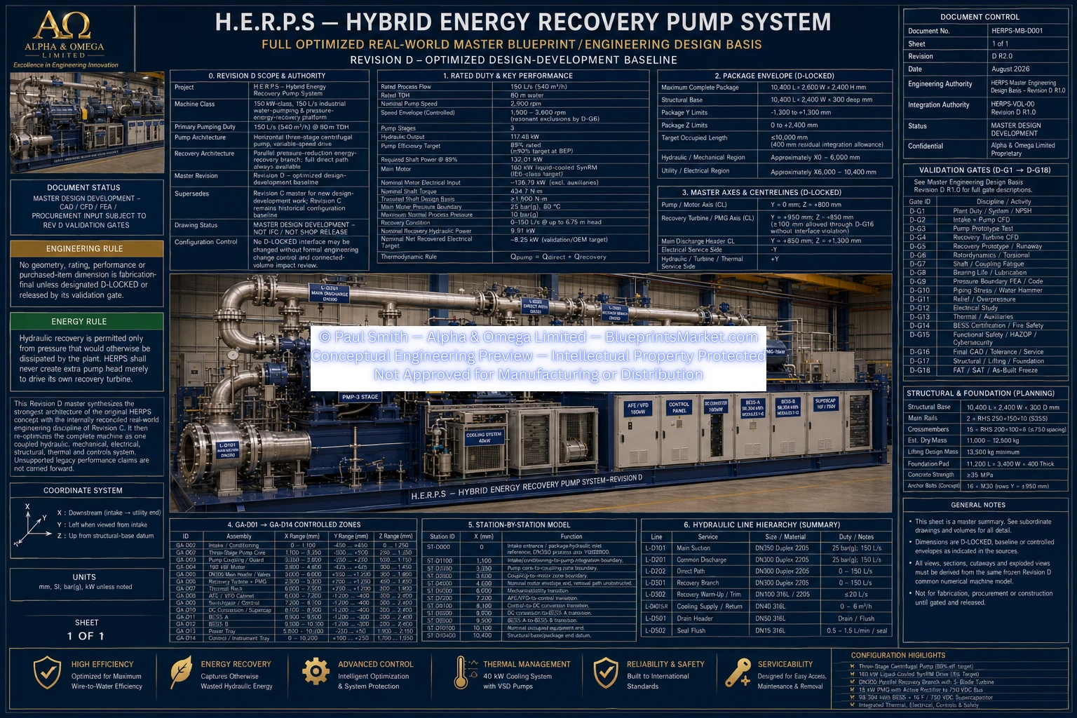
HERPS_MASTER_ENGINEERING_DESIGN_BASIS_REV_D_R2.0.webp
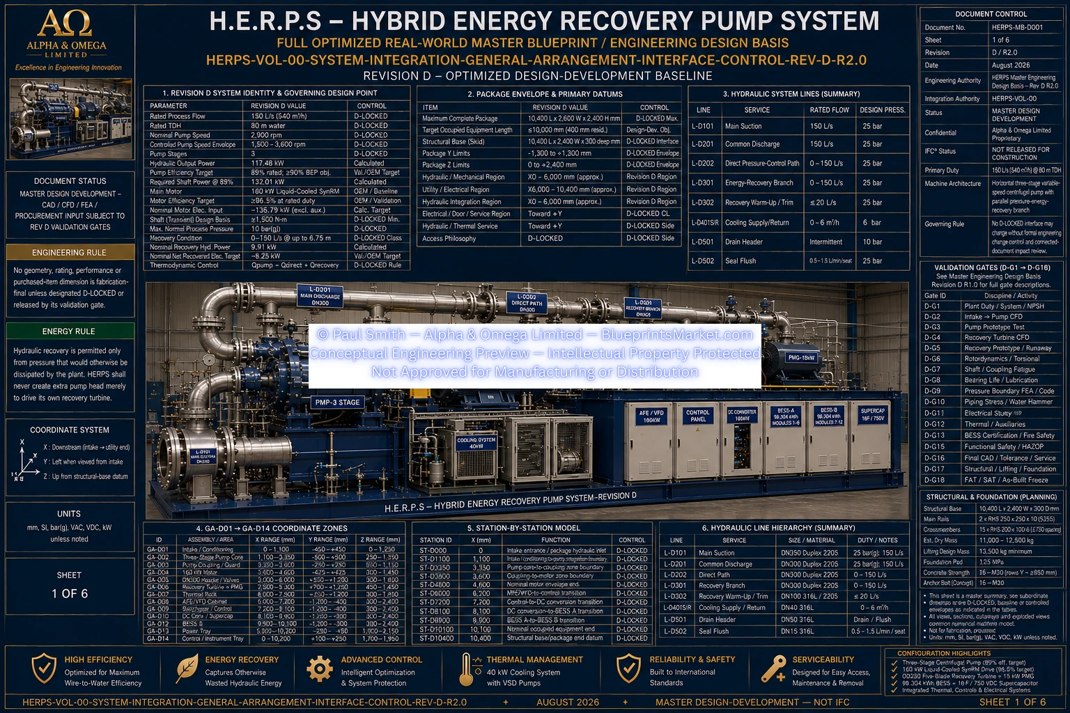
HERPS-VOL-00-SYSTEM-INTEGRATION-GENERAL-ARRANGEMENT-INTERFACE-CONTROL-REV-D-R2.0.webp
Revision D distinguishes between internally reconciled design interfaces, design-development baselines, validation-controlled values, OEM-controlled purchased equipment and site-controlled installation values.
Final hydraulic surfaces, pressure-boundary thicknesses, supplier equipment dimensions, protection settings, certified battery construction and site foundation details are therefore frozen only through their applicable engineering validation processes.
The overall H.E.R.P.S design-development architecture is coordinated, but it is not represented as fabrication-final or issued for construction until the applicable Revision D validation gates have been completed.
H.E.R.P.S is an energy-recovery pumping system, not a self-powering or perpetual-energy machine.
Hydraulic recovery is permitted only where pressure would otherwise be dissipated by the plant process. The system does not intentionally create additional pump head solely to drive the recovery turbine.
This design rule protects the underlying thermodynamic and hydraulic energy balance and keeps the primary pumping function independent of the optional recovery subsystem.
This page provides a public engineering overview of the H.E.R.P.S Revision D R2.0 architecture. It intentionally does not replace the detailed purchaser-controlled engineering volumes, released manufacturing data, supplier-certified equipment records, validation calculations or final signed as-built configuration.
Status: Master Design-Development — CAD / CFD / FEA / procurement inputs remain subject to the applicable Revision D validation gates. Not released for construction.
The complete H.E.R.P.S engineering system extends from system integration, intake and hydraulic-core design through rotating equipment, pressure boundaries, energy recovery, electrical conversion, battery storage, thermal management, controls, functional safety, structural integration, fabrication, installation, validation, commissioning, maintenance and controlled configuration records.
View the Main H.E.R.P.S Product Page
Contact Blueprints Market for product, licensing and engineering-package enquiries.
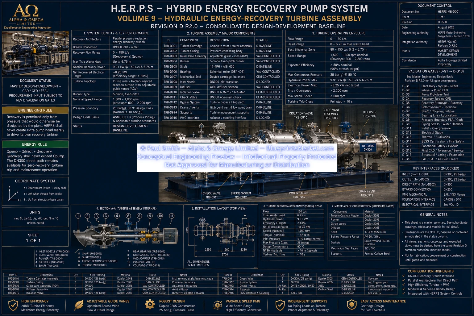
HERPS-VOL-09-HYDRAULIC-ENERGY-RECOVERY-TURBINE-ASSEMBLY-REV-D-R2.0.webp