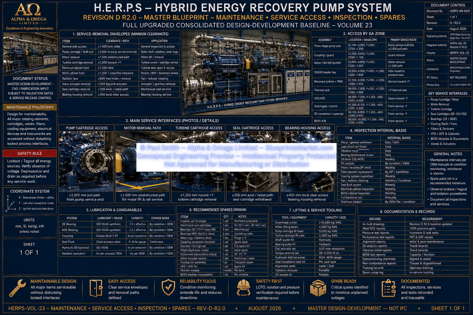
H.E.R.P.S — Maintenance, Service Access, Inspection & Spares
HERPS-VOL-23 — Revision D R2.0
Hybrid Energy Recovery Pump System (H.E.R.P.S)
Revision D Maintenance & Service Architecture
HERPS-VOL-23 defines the maintainable access, isolation, inspection,
service-removal, spare-parts and tooling requirements for the H.E.R.P.S
Revision D R2.0 physical package.
The service architecture is coordinated with the actual Revision D machine
geometry so that pump internals, motor, coupling, recovery turbine, PMG,
thermal rack, electrical cabinets, BESS equipment, valves, instruments and
auxiliary systems can be inspected and serviced without compromising locked
interfaces.
Revision D Service Design Basis
| Parameter |
Revision D R2.0 Basis |
| Machine Class |
160 kW-drive-class horizontal three-stage variable-speed centrifugal industrial water pump with controlled hydraulic-energy-recovery path |
| Rated Duty |
150 L/s at 80 m TDH |
| Rated Pump Speed |
2,900 rpm |
| Maximum Package Envelope |
10,400 L × 2,600 W × 2,400 H mm |
| Maintenance Philosophy |
Condition-based, OEM-controlled and validation-controlled where Revision D does not freeze a value |
Locked Service-Removal Envelopes
| Service Requirement |
Minimum Revision D Clearance |
Application |
| General Side Access |
≥1,000 mm both service sides |
Inspection, leak checks, piping and instrumentation |
| Pump Rotor / Shaft Pull |
≥2,000 mm |
Rotor, shaft, impellers, wear rings and internal pump service |
| Motor Removal |
≥1,500 mm unobstructed |
160 kW motor lifting, removal and rail service |
| Turbine Cartridge Removal |
≥1,200 mm toward +Y |
Runner, shaft, bearing and PMG-side service |
| Electrical Cabinet Front |
≥1,200 mm or local code greater |
AFE/VFD, switchgear, controls and DC conversion |
| BESS Cabinet Front |
≥1,200 mm plus supplier/fire-code requirement |
BMS, module, service-disconnect and HVAC service |
| Radiator Face |
≥600 mm |
Airflow, cleaning and fan/radiator replacement |
| Valve Actuator |
≥300 mm beyond actuator envelope or vendor greater |
Actuator and gearbox removal |
| Seal Cartridge |
≥250 mm |
Mechanical-seal cartridge withdrawal |
| Bearing Housing |
≥400 mm local clear access |
DE/NDE bearing and labyrinth service |
Equipment Access by Revision D GA Zone
- GA-D01 Intake / Conditioning: Withdrawable conditioner and accessible DN350 suction interface.
- GA-D02 Pump Core: Dedicated ≥2,000 mm rotor/shaft extraction corridor.
- GA-D03 Coupling / Guard: Tool-removable guard with spacer-coupling access.
- GA-D04 Motor: ≥1,500 mm unobstructed motor-removal corridor.
- GA-D05 Header / Valves: Side-routed DN300 header to preserve motor-removal axis.
- GA-D06 Recovery / PMG: ≥1,200 mm +Y cartridge-removal route.
- GA-D07 Thermal Rack: Radiator free-face service access.
- GA-D08 AFE / VFD: Cabinet service toward -Y.
- GA-D09 Controls: Control cabinet service toward -Y.
- GA-D10 DC / Supercapacitor: Stored-energy isolation-controlled service zone.
- GA-D11 / GA-D12 BESS: Supplier and fire-code controlled service clearance.
Three-Stage Pump Internal Service Strategy
| Service Item |
Revision D Baseline |
Maintenance Control |
| Pump Shaft |
1,600 mm total stepped shaft; functional diameters 65–85 mm |
Supported extraction through ≥2,000 mm service envelope; protect journals, keyways and fits |
| Impellers |
3 stages; 290–310 mm OD mechanical envelope; nominal target approximately 300 mm |
Mark stage and orientation; do not alter released hydraulic geometry |
| Diffusers |
3 × Duplex 2205 cartridges; OD430 mechanical envelope |
Inspect erosion, corrosion and vane damage |
| Wear Rings |
Target radial running clearance 0.35–0.45 mm subject to validation |
Measure and trend; service limit remains released/OEM controlled |
| Balance Drum |
OD130 × 120; target radial clearance 0.20–0.30 mm |
Inspect wear and clearance against approved axial-thrust criteria |
| Shaft Sleeves |
ID75 H7; OD80 h6; L100 |
Inspect seal track and surface condition |
| Pressure Casing |
Duplex 2205; 25 bar design baseline |
Inspect leakage, corrosion, weld distress and nozzle-loading evidence |
Bearings, Lubrication & Condition Inspection
| Component |
Revision D Baseline |
| DE Bearing |
7314-class angular-contact DB pair, 70 ID × 150 OD × 35 mm each |
| NDE Bearing |
NU314-class cylindrical roller, 70 ID × 150 OD × 35 mm |
| DE Oil Volume |
3.5 L effective |
| NDE Oil Volume |
2.5 L effective |
| Oil Grade |
ISO VG46 baseline |
| Bearing Temperature |
Pt100 monitoring; high-high baseline ≥95 °C or lower supplier limit |
| Axial Movement |
≤0.15 mm steady-state after thermal stabilization |
| Labyrinth |
Shaft diameter 80 mm; radial clearance 0.25–0.35 mm |
Mechanical Seal & Seal-Flush Maintenance
- SE-101/102 balanced SiC/SiC cartridge seals use a ≥250 mm removal path.
- Seal housing must be isolated, depressurized and drained before removal.
- OD80 sleeve sealing tracks are protected during maintenance.
- SF-101 uses a 316L 50-micron replaceable flush filter.
- SF-102/103 restriction/orifice baseline targets approximately 0.5–1.5 L/min per seal.
- Flush isolation valves must be lockable during seal service.
- Seal drains remain clear and abnormal leakage trends must be investigated rather than concealed.
Motor, Coupling & Drive Service
- 160 kW liquid-cooled SynRM development baseline.
- Motor removal uses the locked ≥1,500 mm service corridor.
- Machined motor rails preserve measured shim packs and elevation.
- Disc-pack spacer coupling uses a 180 mm spacer baseline.
- Coupling baseline capacity ≥2,000 N·m continuous and ≥4,000 N·m peak.
- After pump/motor/coupling disturbance, restore alignment to ≤0.05 mm parallel and ≤0.05° angular with approved hot-growth correction.
- 304 stainless-steel perforated guard must be refitted before operation.
- VFD terminals require complete de-energization, lockout and OEM discharge-time compliance.
Recovery Turbine & Generator Service
- DN300 recovery cartridge uses ≥1,200 mm removal toward +Y.
- Direct hydraulic path must remain available before recovery equipment is isolated for service.
- Ten adjustable guide vanes cover the 0–25° command range.
- Super Duplex 2507 fixed-pitch five-blade runner uses a nominal OD250 development envelope.
- Runner and guide geometry must not be reprofiled outside the released engineering configuration.
- Turbine shaft uses the released dimensional and runout criteria.
- PMG baseline is 15 kW with approximately 180 kg handling allowance.
- Active rectifier is treated as high-voltage stored-energy equipment connected to the 750 VDC common link.
- DN300 non-slam check valve is inspected for reliable reverse-flow prevention.
Valve, Actuator, Meter & Pressure-System Access
- XV-101: DN350 suction isolation.
- XV-201: DN300 discharge isolation with electric and manual operation.
- CV-201: DN300 non-slam check valve.
- FCV-201: DN300 modulating flow-control valve with fail-open baseline.
- PSV-201: Mechanical relief independent of PLC control.
- FT-101 / FT-301: Main and recovery flowmeters maintained under the metrology program.
- Pressure instruments use safe root-valve/manifold isolation.
- High-point vents and low-point drains remain functional, accessible and safely routed.
Thermal Rack, Radiator, Fan & Filter Service
| Component |
Revision D R2.0 Baseline |
| Radiator |
40 kW; 1,400 W × 900 D × 1,100 H mm; two EC fans |
| Radiator Service Clearance |
≥600 mm free face |
| Plate Heat Exchanger |
316L; 40 kW; DN40 |
| Cooling Pumps |
2 — duty + standby; 0–6 m³/h maximum at approximately 2.5 bar |
| Expansion Tank |
50 L diaphragm; 6 bar |
| Reservoir |
80 L 316L baffled |
| Cooling Filter |
100 micron |
| 3-Way Valve |
DN40 modulating |
Electrical Cabinet, DC-Link & BESS Isolation
- Apply LOTO to all possible electrical and stored-energy sources.
- Sources include plant 400 VAC, AFE/VFD, PMG/rectifier, BESS, supercapacitor and auxiliary/control supplies.
- Automatic restart must be inhibited.
- OEM discharge time must be observed before testing for absence of voltage.
- Absence of voltage must be proven using appropriately rated verified test equipment.
- BESS service requires manual-service-disconnect, contactor, HVIL and IMD verification.
- Supercapacitor/DC-link residual voltage must be physically verified rather than inferred from HMI indication.
- Cabinet fronts require ≥1,200 mm clearance or the greater local-code requirement.
Inspection & Maintenance Interval Framework
Revision D deliberately does not invent universal calendar or operating-hour
replacement intervals where equipment manufacturers, operating conditions,
statutory requirements or actual condition data must determine the final service interval.
- Continuous / Online: Trend hydraulic pressures, flows, speeds, bearing temperatures, vibration, cooling, DC-link and BMS status.
- Routine Operating Round: Visual leak, noise, temperature, vibration, cooling, guards and cabinet condition.
- After First Commissioning: Recheck leakage, alignment trends, oil, filters, fasteners and instruments as required.
- Condition-Based: Service oil, bearings, seals, wear rings, filters, valves, fans and cooling surfaces according to measured condition or OEM threshold.
- Planned Outage: Intrusive pump/turbine inspection, coupling alignment and valve/electrical maintenance as required.
- Statutory / Certified: Pressure relief, pressure systems, electrical protection, BESS/fire systems and lifting gear follow mandatory intervals.
- After Trip / Abnormal Event: Inspect affected subsystem before return to service.
- After Major Maintenance: Repeat relevant alignment, leak, pressure, electrical and FAT/SAT functional checks.
Condition-Based Inspection Points
| Subsystem |
Trend / Inspect |
Escalation Condition |
| Pump Hydraulics |
Q-H/power deviation, suction margin, cavitation signature |
Material deviation from accepted performance or new cavitation behavior |
| Rotor / Bearings |
Vibration spectrum, bearing temperature, axial movement, oil debris |
New resonance, rising trend, threshold exceedance or abnormal debris |
| Mechanical Seals |
Leak rate, flush pressure, filter condition |
Rising leakage, inadequate flush or face heating/damage |
| Pressure Boundary |
Leakage, corrosion, weld and nozzle distress |
Any pressure-boundary leak or deformation |
| Recovery Turbine |
Power versus flow/head, vibration, speed and runner condition |
Efficiency loss, cavitation, overspeed event or unstable guide control |
| Cooling |
Flow, temperature, fouling and fan/pump condition |
Low-flow state or rising approach temperatures |
| Electrical |
Thermal condition, alarms, insulation, earth and bonding |
Hot joint, insulation fault, repeated trip or protection anomaly |
| BESS |
Cell delta-V/T, SOC/SOH, insulation and thermal/off-gas alarms |
Supplier threshold, imbalance or insulation/fire signal |
Recommended Mechanical & Hydraulic Operational Spares
- 1 complete mechanical seal cartridge per installed type; consider 2 where outage criticality warrants.
- 1 pair of replaceable shaft sleeves.
- 1 complete three-stage set of casing/impeller wear rings.
- At least 1 complete pump-opening gasket set.
- 1 matched DE angular-contact bearing pair.
- 1 NDE cylindrical-roller bearing.
- 1 pair of labyrinth seals.
- 1 coupling disc/fastener service kit.
- Multiple 50-micron seal-flush filter elements.
- Critical valve packing, seal and actuator kits after vendor selection.
- Selected critical calibrated flow/pressure instrument spares.
- Multiple 100-micron cooling-filter elements.
Recommended Electrical, Thermal & BESS Spares
- 1 EC radiator fan assembly.
- 1 service-ready cooling pump or critical repair kit where site criticality requires.
- Selected temperature, pressure and flow sensor spares.
- 1 spare 24 VDC PSU.
- 1 spare of each critical PLC/I/O module type.
- 1 configured HMI spare or verified recovery image.
- OEM-recommended AFE/VFD critical fan, control or power-module strategy.
- OEM-recommended DC/DC and rectifier modules.
- No generic loose-cell BESS spare is prescribed.
- BESS replacement strategy remains supplier-certified.
- OEM-recommended supercapacitor/converter spares.
- BESS cabinet HVAC filters, fans and critical controller spares as applicable.
Lifting & Service Tooling
- D-G17-approved package lifting configuration using qualified primary and auxiliary lifting points.
- Certified spreaders, slings and shackles sized from the approved lift analysis.
- Motor handling equipment compatible with approximately 1,100 kg motor allowance and OEM lift points.
- PMG handling equipment compatible with approximately 180 kg allowance.
- Supported rotor/shaft extraction equipment using the ≥2,000 mm pull corridor.
- Turbine cartridge cradle or hoist using the ≥1,200 mm +Y removal route.
- Laser shaft-alignment system.
- Calibrated torque/tension tooling.
- Bearing induction heater or supplier-approved installation tools.
- Mechanical-seal cartridge setting and clean-face handling tools.
- Appropriately rated HV test equipment, proving unit, lockout equipment and discharge-verification tools.
- Calibrated pressure gauges, blinds, caps and controlled depressurization equipment.
Maintenance Safety & Lockout Interfaces
| Hazard |
Required Isolation / Control |
| Rotating Pump / Motor |
Torque inhibit, upstream lockable electrical isolation, zero-speed verification and restart prevention |
| Pressurized Water |
Close required isolations, lock/tag, depressurize, vent, drain and verify zero pressure |
| Recovery Turbine |
Isolate DN300 recovery path, secure admission system, confirm direct path and zero turbine speed |
| DC Link / Supercapacitor |
Isolate all AC/DC sources, discharge and prove absence of voltage |
| BESS |
Certified manual service disconnect, HVIL and contactor isolation process |
| Cooling Circuit |
Isolate, cool, depressurize and drain affected branch |
| Lifting |
Use approved lifting points and establish controlled exclusion zone |
| Guards / Interlocks |
Remove only under LOTO and verify restoration before operation |
Post-Maintenance Reassembly & Return to Service
- Confirm correct parts, materials, orientation, fits, gaskets and locking features.
- Restore oil levels, seal flush, cooling, vents, drains and instrument root valves.
- Refit all guards and safety devices.
- Restore pump/motor/coupling alignment after disturbance.
- Perform applicable pressure, leak or NDE checks after pressure-boundary work.
- After electrical work, verify bonding, insulation, continuity, phase/rotation and functional operation.
- After BESS/DC service, verify HVIL, IMD, precharge, contactors and communications.
- Perform controlled low-load return while trending vibration, temperatures, leakage, cooling and electrical data.
- Update maintenance records, replaced-part serials, calibration status and engineering-change records.
Maintenance Record Minimum Data Set
- Asset/tag and equipment serial number
- Date, accumulated runtime and starts where available
- Maintenance reason and work-order classification
- LOTO / isolation permit and verified zero-energy state
- As-found condition
- Work performed
- Replacement part numbers and critical batch/serial data
- Alignment, runout, clearance, torque/tension and calibration measurements
- As-left condition and restored settings
- Leak, pressure, rotation, functional and interlock testing completed
- Technician and verifier / engineer release signatures
Validation Gates Affecting Maintenance Finalization
- D-G3: Pump hydraulic acceptance and degradation criteria.
- D-G6: Rotordynamic prohibited bands and vibration interpretation.
- D-G8: Bearing life, preload, endplay and replacement strategy.
- D-G9: Pressure-boundary inspection and repair requirements.
- D-G11: Certified relief-device service requirements.
- D-G4 / D-G5: Recovery turbine wear, cavitation and service criteria.
- D-G12: Electrical fault, protection, arc-flash and PPE requirements.
- D-G14: BESS certified replacement, storage, isolation and fire-safety procedures.
- D-G15: Final lockout interfaces, fail states and proof-test requirements.
- D-G16: Final CAD service envelopes and vendor-specific access freeze.
- D-G17: Certified lifting points and handling plan.
- D-G18: FAT/SAT/as-left performance and controls baseline for condition monitoring.
No False Maintenance Finalization
Revision D does not invent universal calendar or operating-hour replacement
intervals, certified vendor spare-part numbers, final bearing L10 life,
certified BESS module service procedures, final valve-actuator dimensions,
final electrical arc-flash boundaries or final lifting rigging.
Those requirements are finalized through OEM documentation, condition monitoring,
validation gates, statutory requirements, commissioning records and actual site
operating history.
Explore the Complete H.E.R.P.S Revision D System
Maintenance, Service Access, Inspection & Spares forms part of the complete
H.E.R.P.S Revision D multi-volume conceptual engineering blueprint system.
View the Complete HERPS System
Contact Blueprints Market for product,
licensing and engineering-package enquiries.
© Paul Smith — Alpha & Omega Limited — PlatformClouds.com — Conceptual Engineering Preview — Not Approved for Manufacturing
HERPS-VOL-23-MAINTENANCE-SERVICE-ACCESS-INSPECTION-SPARES-REV-D-R2.0.webp
