
H.E.R.P.S — Recovery PMG, Active Rectifier & Generator Drive
HERPS-VOL-10 — Revision D R2.0
Hybrid Energy Recovery Pump System (H.E.R.P.S)
Permanent-magnet synchronous generation, hydraulic recovery drivetrain integration, controlled active rectification and common-DC-link energy conversion.
Revision D Recovery Generator System Overview
H.E.R.P.S Volume 10 defines the Revision D electrical conversion architecture that transforms available mechanical shaft power from the hydraulic energy-recovery turbine into controlled electrical energy for the H.E.R.P.S common DC power system.
The subsystem integrates the recovery permanent-magnet synchronous generator, turbine-to-generator mechanical interface, generator mounting and alignment, electrical terminals, thermal monitoring, variable-frequency three-phase power output, active rectification, generator-side isolation and protection, DC-link injection, electrical bonding and coordinated fault-management interfaces.
- Permanent-magnet synchronous recovery generator
- Hydraulic turbine-to-generator drivetrain interface
- Flexible coupling and alignment architecture
- Variable-voltage, variable-frequency three-phase generation
- 20 kW-class controlled active rectification
- 750 VDC nominal common-link integration
- Generator and converter thermal monitoring
- Electrical isolation and protective bonding
- Overspeed and DC overvoltage coordination
- Industrial EMC and cable-segregation architecture
Hydraulic Pressure Energy Converted Into Electrical Energy
The H.E.R.P.S recovery generator operates only when the connected hydraulic system contains genuine pressure head that would otherwise be dissipated by the plant. Available hydraulic energy is converted to turbine shaft power and then transferred mechanically into the permanent-magnet generator.
At the Revision D governing reference condition, the recovery architecture considers up to 150 L/s of controlled recovery flow where as much as approximately 6.75 m of genuine otherwise-wasted hydraulic head is available.
This represents approximately 9.91 kW of hydraulic power at the stated reference condition before turbine, generator and conversion losses. The associated nominal recovered-electrical development target is approximately 8.25 kW, subject to actual hydraulic conditions and validation.
H.E.R.P.S RECOVERS ONLY GENUINE OTHERWISE-WASTED HYDRAULIC PRESSURE ENERGY. IT DOES NOT CREATE ADDITIONAL HYDRAULIC HEAD TO POWER ITS OWN GENERATOR.
Permanent-Magnet Synchronous Recovery Generator
Revision D uses a permanent-magnet synchronous generator as the electrical machine coupled to the hydraulic recovery turbine.
The public Revision D design-development baseline specifies a 15 kW minimum continuous PMG rating. An optional 18 kW same-envelope vendor frame may be considered where it produces no integration, efficiency or serviceability penalty.
- Permanent-magnet synchronous generator architecture
- 15 kW minimum continuous rating
- Optional 18 kW same-envelope vendor configuration
- 600–2,200 rpm continuous development range
- 1,500–1,800 rpm nominal development target
- Variable-voltage, variable-frequency three-phase AC output
- High-efficiency generator development target
- No direct PMG-to-grid connection
High-Efficiency PMG Development Target
Revision D raises the recovery-generator efficiency objective to ≥96% within the nominal 8–10 kW mechanical-input region.
This is an engineering development target rather than a guaranteed production value. Final generator efficiency must be established from selected-vendor data and measured validation across the released operating speed and load map.
Recovery Turbine-to-PMG Generator Drive
Mechanical power from the Revision D hydraulic energy-recovery turbine is transmitted to the PMG through a coordinated flexible-coupling architecture.
The turbine and generator remain on a common controlled rotating axis, while the support arrangement allows accurate alignment, soft-foot correction, coupling inspection and service access.
- Common turbine-generator rotating axis
- Flexible coupling architecture
- Precision mechanical alignment
- Soft-foot verification
- Tool-removable coupling guarding
- Alignment re-verification following piping and support integration
- Service access for turbine, PMG and coupling components
20 kW Active Rectifier & Controlled Generator Conversion
Variable-frequency three-phase electrical output from the PMG is supplied to the Revision D active rectifier, which controls generator electromagnetic loading and converts the recovered AC power into regulated DC energy.
The active rectifier has a Revision D minimum continuous rating of 20 kW, providing conversion margin above the nominal hydraulic recovery operating region.
- 20 kW minimum active-rectifier rating
- Variable-frequency three-phase PMG input
- Controlled generator electromagnetic loading
- Nominal ≥98.5% conversion-efficiency development target
- Controlled DC output into the H.E.R.P.S common link
- DC overvoltage coordination
- Generator and converter isolation architecture
- Industrial protection and monitoring interfaces
750 VDC Common-Link Energy Integration
Rectified recovery energy is transferred into the H.E.R.P.S common DC architecture rather than being directly connected to the AC utility grid.
Revision D uses a nominal 750 VDC common-link architecture with a controlled operating window coordinated across the generator rectifier, main drive, DC conversion, battery-energy storage and supercapacitor subsystems.
- 750 VDC nominal common-link architecture
- Controlled DC operating window
- Active recovered-power injection
- Coordinated DC overvoltage protection
- Common-link insulation monitoring interface
- BESS and supercapacitor interoperability
- Internal recovery-energy routing
- Grid export disabled by default
Controlled Recovery Operating Modes
The generator-drive system operates through defined control states so that hydraulic process requirements remain more important than electrical energy recovery.
- Standby / No Recovery: generator recovery torque inhibited.
- Recovery Enable: electrical and hydraulic permissives verified before loading.
- Normal Recovery: PMG torque coordinated with hydraulic recovery conditions.
- Low Recoverable Head: PMG unloading and reduction of hydraulic recovery admission.
- DC-Link High: recovered-power injection reduced or inhibited.
- Turbine Overspeed: coordinated hydraulic admission reduction and electrical unloading.
- Generator / Converter Fault: affected recovery electrical branch isolated while primary process continuity is preserved where safe.
- Maintenance Isolation: verified electrical isolation before servicing.
Overspeed Protection & Electrical Unloading
Revision D does not rely on generator electrical loading as the sole method of controlling turbine overspeed.
Recovery-train protection coordinates hydraulic admission, the direct hydraulic process path, PMG electrical loading and converter isolation so that loss of the generator or DC-energy sink cannot create an uncontrolled recovery condition.
Final overspeed limits remain validation-controlled through the Revision D turbine runaway and system-safety test program.
Generator Electrical Protection & Isolation
The PMG and active rectifier operate as an industrial electrical generation and conversion subsystem and therefore require coordinated isolation, overcurrent protection, bonding, stored-energy controls and fault handling.
- Lockable generator-side isolation
- Generator overcurrent and fault protection
- Active rectifier fault isolation
- DC-side isolation
- DC overvoltage coordination
- Protective bonding and earthing
- Insulation monitoring
- Touch protection and guarding
- Stored-energy warnings and controlled discharge procedures
PMG & Active Rectifier Thermal Management
Generator and converter losses are incorporated into the Revision D machine thermal architecture. The PMG uses an OEM-controlled cooling configuration compatible with the coordinated installation envelope, while converter thermal management is matched to selected equipment and operating conditions.
- PMG temperature monitoring
- Generator winding / bearing / frame temperature sensing as required
- Active rectifier thermal monitoring
- OEM-defined cooling requirements
- Ambient and altitude derating consideration
- Cooling-airflow obstruction prevention
- System thermal validation before final release
EMC, Cabling & Signal Segregation
Revision D separates generator power cabling from low-level speed, temperature, vibration and control instrumentation to reduce electromagnetic interference and preserve reliable machine monitoring.
- Dedicated PMG-to-rectifier power pathway
- Segregated low-noise instrumentation routing
- Shielding and armour where required
- Dedicated protective-earth architecture
- Industrial converter-duty cable requirements
- Cable routing coordinated with maintenance access
- Final cable sizing determined by engineering study and selected equipment
Generator Performance & Condition Monitoring
Revision D supports synchronized measurement of hydraulic, mechanical and electrical conditions so the actual energy-conversion chain can be evaluated across the released recovery operating map.
- Recovery turbine speed
- Generator speed
- PMG temperature
- Recovery-train vibration
- PMG AC electrical power
- Active-rectifier DC output
- Common-link voltage and current
- Hydraulic recovery flow and available pressure head
- Measured generator efficiency
- Measured rectifier conversion efficiency
- Net recovered electrical power
Internal Recovery Energy Routing — No Default Grid Export
Recovered energy is routed internally through the H.E.R.P.S common DC architecture. The recovery PMG does not connect directly to the utility grid as part of the standard Revision D configuration.
Grid export is disabled by default. Any future export capability would require a separately engineered and approved electrical interconnection and protection system.
Serviceability, Alignment & Maintenance
The Revision D recovery generator assembly is designed so the PMG, coupling, coupling guard, terminal connections and active rectifier remain serviceable without dismantling unrelated permanent machine systems.
- PMG removal access
- Tool-removable coupling guard
- Coupling alignment access
- Soft-foot inspection
- Terminal-box service access
- Converter service isolation
- Cooling-system inspection
- Post-maintenance bonding and insulation checks
- Configuration-controlled firmware and protection settings
Revision D Validation & Design Freeze
The recovery PMG, active rectifier and generator-drive system remains subject to formal Revision D validation before fabrication-final or as-built release.
Validation covers recovery-turbine runaway behaviour, rotordynamic and torsional compatibility, shaft and coupling loads, electrical protection, harmonics and EMC, generator and converter thermal performance, functional safety, final equipment fit, service clearances and integrated FAT/SAT acceptance.
Final supplier-specific generator electromagnetic construction, shaft details, converter internals, conductor sizes, protective-device settings and certified equipment characteristics are intentionally not invented or represented as frozen public specifications.
Cross-System H.E.R.P.S Integration
Volume 10 interacts directly with the hydraulic recovery turbine, common DC-link, AFE/VFD power architecture, battery-energy storage, PLC/HMI/SCADA instrumentation, functional-safety system, structural supports, installation process and validation program.
- Hydraulic Energy-Recovery Turbine Assembly
- AFE / VFD / Switchgear & AC Power Distribution
- Common DC Link / DC-DC Conversion / Supercapacitor System
- BESS Cabinets & Battery Safety
- PLC / HMI / SCADA & Instrumentation
- Functional Safety & Hardwired Trips
- Structural Skid & Equipment Supports
- Assembly, Installation & Alignment
- Engineering Validation & Design Freeze
- FAT / SAT & Commissioning
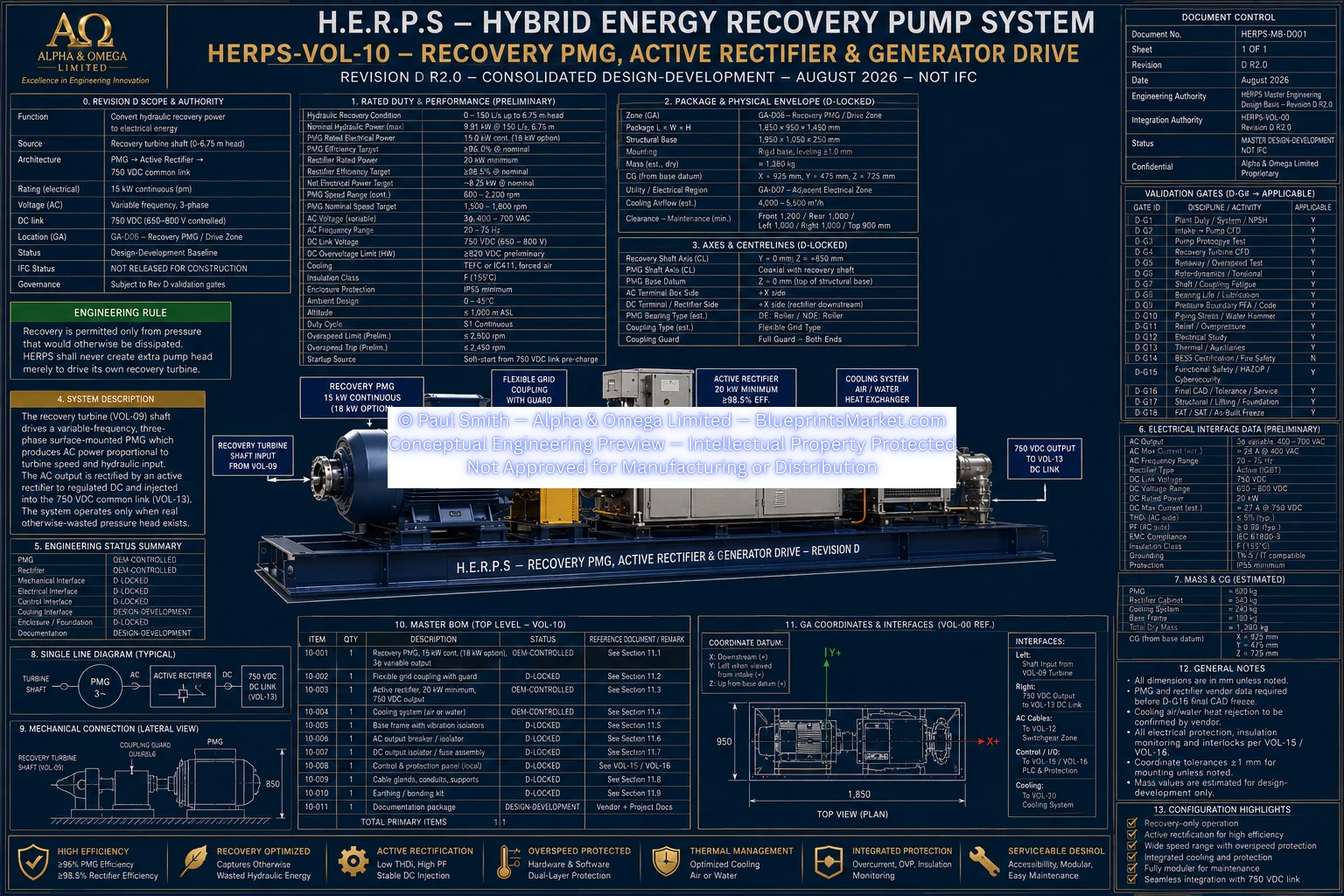
HERPS Volume 10 — Revision D Blueprint Preview
The following watermarked engineering blueprint provides the public visual preview for the H.E.R.P.S Revision D Recovery PMG, Active Rectifier & Generator Drive system.
H.E.R.P.S Revision D Blueprint Access & Licensing
Recovery PMG, Active Rectifier & Generator Drive is Volume 10 of the complete H.E.R.P.S Revision D R2.0 engineering documentation architecture.
The complete H.E.R.P.S engineering system spans hydraulic pumping, rotating equipment, energy recovery, electrical conversion, thermal management, energy storage, industrial automation, functional safety, structural engineering, installation, validation, commissioning, maintenance and configuration control.
View Complete H.E.R.P.S Revision D System
View Blueprint Package & Pricing | View Licensing | Contact Blueprints Market
Engineering Development Notice
H.E.R.P.S Revision D R2.0 is a controlled consolidated design-development engineering baseline and is not represented as an IFC construction release, fabrication-final drawing set, supplier-certified production design or measured as-built configuration.
Final PMG electromagnetic geometry, winding and pole data, shaft-extension details, generator bearings, converter semiconductor topology, final cable sizes, protection settings, certified enclosure information and measured efficiency, thermal and overspeed performance remain subject to OEM selection and the applicable Revision D engineering validation gates.