© Paul Smith — Alpha & Omega Limited — PlatformClouds.com — Conceptual Engineering Preview — Not Approved for Manufacturing
HERPS-VOL-00-SYSTEM-INTEGRATION-GENERAL-ARRANGEMENT-INTERFACE-CONTROL-REV-D-R2.0.webp

H.E.R.P.S — HYBRID ENERGY RECOVERY PUMP SYSTEM
System Integration • General Arrangement • Interface Control • Revision D — R2.0
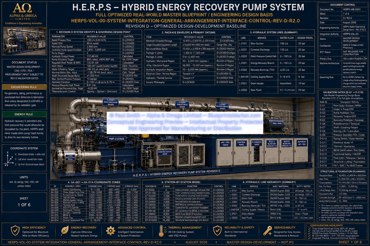
This engineering section presents the integrated H.E.R.P.S machine architecture as a coordinated system, bringing the hydraulic, mechanical, energy-recovery, electrical, energy-storage, thermal-management, control, structural and site-interface systems into the common Revision D machine arrangement.
The Revision D system-integration architecture establishes the common physical and functional arrangement used to coordinate the major H.E.R.P.S subsystems. The integrated machine includes the three-stage pump and drive train, suction and discharge flow paths, recovery branch, recovery turbine and permanent-magnet generator, electrical conversion and DC-link architecture, energy storage, supercapacitor support, thermal management, PLC/HMI/SCADA controls, structural skid and associated installation interfaces.
This page is therefore the system-level integration reference rather than an isolated component page. It shows how the individual H.E.R.P.S subsystem volumes relate to the complete assembled machine and its defined interfaces.
Integrated suction, three-stage pumping, common discharge, direct process path and controlled energy-recovery flow path.
Three-stage centrifugal pump architecture coordinated with the variable-speed synchronous reluctance motor drive and associated mechanical support systems.
Recovery turbine and permanent-magnet generator integrated with the hydraulic recovery branch and electrical conversion architecture.
Coordinated plant electrical interface, power conversion, common DC-link, BESS, supercapacitor and controlled energy-flow architecture.
PLC, HMI and SCADA functions integrated with process instrumentation, protection, operating permissives, alarms and system sequencing.
Pump, motor, turbine-generator equipment, piping, auxiliaries and electrical equipment coordinated with the common structural skid and installation interface architecture.
| System Flow | 150 L/s |
|---|---|
| Total Dynamic Head | 80 m TDH |
| Main Pump | Three-stage centrifugal pump |
| Development Drive Baseline | 160 kW SynRM |
| Main Suction | DN350 |
| Common Discharge | DN300 |
| Recovery Branch | DN300 |
| Electrical Common Link | 750 VDC |
| Energy Storage | BESS with supercapacitor support |
| Supervisory Control | PLC / HMI / SCADA architecture |
HERPS-VOL-00-SYSTEM-INTEGRATION-GENERAL-ARRANGEMENT-INTERFACE-CONTROL-REV-D-R2.0.webp
The system-integration volume provides the common reference for coordinating equipment location, hydraulic connectivity, electrical interfaces, controls, thermal-management connections, structural mounting, service access and site-interface requirements across the H.E.R.P.S Revision D engineering set.
Detailed component construction, tolerances, fabrication requirements, installation procedures, commissioning requirements and subsystem-specific engineering remain controlled by their corresponding Revision D volumes.
Revision: D — R2.0
Document Class: System Integration / General Arrangement / Interface Control
Engineering Status: Conceptual Engineering Preview — Not Approved for Manufacturing