© Paul Smith — Alpha & Omega Limited — PlatformClouds.com —
Conceptual Engineering Preview — Not Approved for Manufacturing
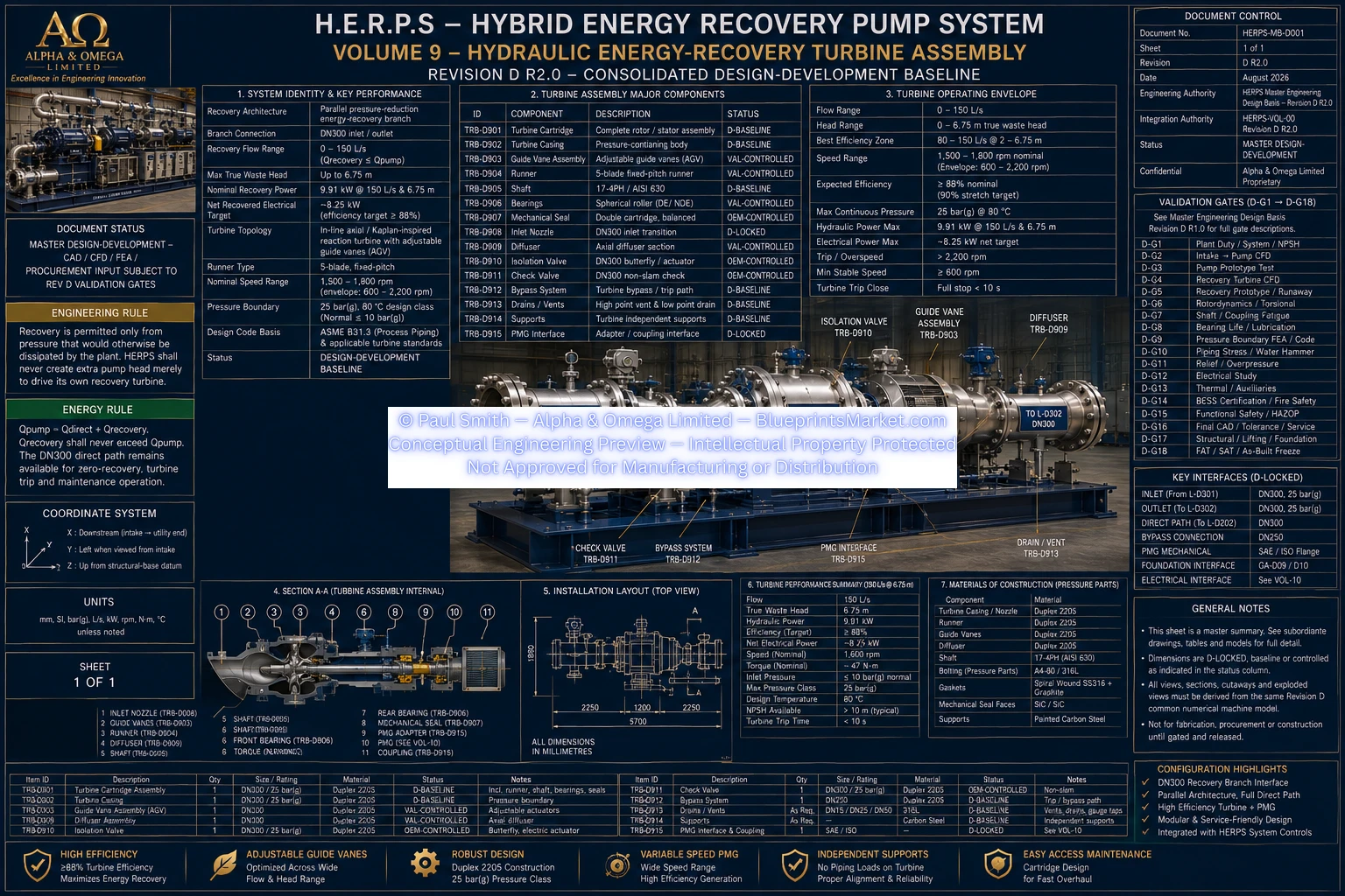
HERPS-VOL-09-HYDRAULIC-ENERGY-RECOVERY-TURBINE-ASSEMBLY-REV-D-R2.0.webp

H.E.R.P.S — HYBRID ENERGY RECOVERY PUMP SYSTEM
HERPS-VOL-09 + HERPS-VOL-10 — Revision D R2.0
The H.E.R.P.S Revision D recovery train converts genuine otherwise-wasted hydraulic pressure into useful electrical energy through a parallel DN300 recovery branch, an axial/Kaplan-inspired reaction turbine, variable-speed permanent-magnet generator and active rectifier.
The direct DN300 process path remains available at all times so that energy recovery cannot compromise required process flow, pressure or primary pump stability.
DN300 Duplex 2205.
0–150 L/s, with Qrecovery ≤ Qpump.
Up to 6.75 m of genuine otherwise-wasted head.
9.91 kW at 150 L/s and 6.75 m.
Approximately 8.25 kW nominal target only at the stated true-waste-head condition.
Full-capacity DN300 direct path remains available whenever recovery is unavailable or inappropriate.
| Parameter | Revision D R2.0 Baseline |
|---|---|
| Turbine Topology | In-line axial/Kaplan-inspired reaction turbine |
| Runner Type | Fixed-pitch reaction runner |
| Runner Blades | 5 development baseline; CFD sensitivity 4–7 |
| Runner OD | 250 mm nominal development value |
| Runner Hub | Approximately 95 mm |
| Hydraulic Throat | ≥253 mm nominal |
| Minimum Development Tip Clearance | ≥1.5 mm radial |
| Runner Material | Super Duplex 2507 |
| Housing / Guide Material | Duplex 2205 |
10 adjustable vanes.
0–25°.
Meter and condition recovery flow entering the turbine runner.
Guide position is coordinated with downstream pressure, turbine speed and PMG electromagnetic torque.
Move turbine admission toward safe minimum while the direct process path establishes required flow.
| Nominal Development Speed | 1,500–1,800 rpm |
|---|---|
| Controlled Development Envelope | 600–2,200 rpm |
| Speed Measurement | ST-D301 — 0–3,000 rpm |
| Preliminary Hardware Overspeed Trip | ≤2,500 rpm pending final D-G5 runaway validation |
DN300.
25 bar(g), 80 °C.
≤10 bar(g).
Approximately 850–950 mm development envelope.
DN300 return diffuser with ≤10° included expansion angle where hydraulic expansion is required.
| Interface | Revision D Control |
|---|---|
| Recovery Axis | Y=+950 mm, Z=+850 mm nominal |
| GA-D06 X Zone | 2,500–5,300 mm |
| GA-D06 Y Zone | +700 to +1,250 mm |
| GA-D06 Z Zone | 450–1,450 mm |
| Turbine Cartridge Removal | ≥1,200 mm toward +Y |
| PMG Removal | ≥800 mm local pull/lift or OEM greater |
| Generator Parameter | Revision D R2.0 Requirement |
|---|---|
| Type | Permanent-magnet synchronous generator |
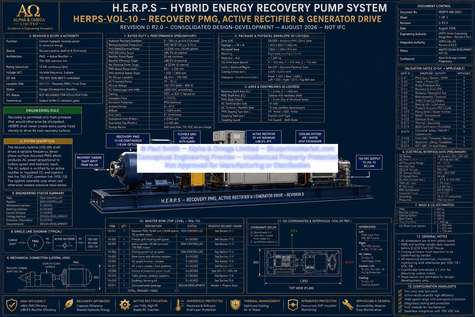
| Continuous Rating | 15 kW minimum |
| Optional Rating | 18 kW only if same-envelope fit produces no integration penalty |
| Mechanical Input Region | 8–10 kW nominal target region |
| Efficiency Target | ≥96% at nominal 8–10 kW mechanical input |
| Speed Range | 600–2,200 rpm development range |
| Output | Variable-voltage, variable-frequency three-phase AC |
| Mounting | Horizontal, foot-mounted |
| Cooling | OEM air-cooled baseline or approved equivalent |
| Parameter | Revision D R2.0 Requirement |
|---|---|
| Type | Controlled active rectifier / generator converter |
| Continuous Rating | 20 kW minimum |
| AC Input | Variable-frequency 3-phase PMG output |
| DC Output | 750 VDC nominal common link |
| Controlled DC Window | 650–800 VDC |
| Efficiency Target | ≥98.5% nominal |
| Preliminary Hardware OVP | ≥820 VDC, final coordination validation-controlled |
Mechanical turbine output drives the PMG through a flexible coupling. The PMG produces variable-voltage, variable-frequency three-phase AC, which is converted by the active rectifier into the H.E.R.P.S 750 VDC common link.
The default Revision D architecture does not directly grid-tie the recovery PMG. Recovered energy is routed internally through the common DC architecture.
Grid export is disabled by default and would require a separately engineered and approved interconnection and protection system.
The control system may not increase the main pump pressure setpoint solely to create additional turbine recovery.
| Tag / Measurement | Revision D Requirement |
|---|---|
| PT-D301 / PT-D302 | Recovery pressure before/after turbine — 0–25 bar(g) |
| FT-D301 | Recovery flow — 0–180 L/s |
| ST-D301 | Turbine speed — 0–3,000 rpm independent trip input |
| Vibration | Turbine bearing / support vibration monitoring |
| Temperature | Bearing / PMG and required recovery-train temperatures |
| Electrical KPIs | PMG power, DC voltage/current and rectifier status |
| Component | Revision D Material |
|---|---|
| Runner | Super Duplex 2507 |
| Housing / Guide System | Duplex 2205 |
| DN300 Wetted Recovery Parts | Duplex 2205 baseline |
| DN100 Trim | 316L / Duplex 2205 |
| Coupling Guard | 304 stainless steel |
| Structural Supports / Rails | S355 structural steel family |
The Revision D documents deliberately do not treat final blade surfaces, shaft geometry, bearing sizes, bearing preload, pressure-wall thickness, runaway speed, final overspeed trip, PMG electromagnetic construction, generator shaft extension, winding and pole data, rectifier semiconductor topology, cable sizes or final protection settings as already frozen.
Those values remain controlled by CFD, prototype testing, rotordynamics, shaft-fatigue analysis, bearing-life analysis, pressure-code/FEA, electrical studies, HAZOP, final CAD, selected-vendor data and FAT/SAT.
Revision D R2.0 Consolidated Design-Development — Not IFC — Not Shop Release.
HERPS-VOL-09-HYDRAULIC-ENERGY-RECOVERY-TURBINE-ASSEMBLY-REV-D-R2.0.webp
HERPS-VOL-10-RECOVERY-PMG-ACTIVE-RECTIFIER-AND-GENERATOR-DRIVE-REV-D-R2.0.webp