Intake & Flow Conditioning
DN350 suction architecture incorporating the bell-mouth intake, removable anti-vortex/debris grid, suction transition, validation-controlled flow-straightening cassette, pre-rotation correction vanes and pump inlet spool.

H.E.R.P.S — REVISION D R2.0
H.E.R.P.S is a Revision D design-development industrial water-pumping and pressure-energy-recovery platform engineered around a horizontal three-stage variable-speed centrifugal pump and a controlled parallel pressure-energy-recovery branch.
The Revision D R2.0 master architecture integrates the primary pump, 160 kW liquid-cooled motor baseline, direct pressure-control path, recovery turbine and generator train, thermal management equipment, electrical conversion equipment, energy-storage systems, instrumentation, automation and structural skid into one coordinated machine package.
The complete H.E.R.P.S package is organized around a common Revision D coordinate model so that the hydraulic, rotating, electrical, thermal and structural systems remain physically coordinated throughout the machine.
The maximum complete package envelope is 10,400 mm long × 2,600 mm wide × 2,400 mm high. The structural base is 10,400 mm long × 2,400 mm wide × 300 mm deep.
The hydraulic and mechanical equipment occupies approximately X0–6,000, while the thermal, power-conversion, control and energy-storage equipment extends through the utility/electrical integration region toward X10,400.
DN350 suction architecture incorporating the bell-mouth intake, removable anti-vortex/debris grid, suction transition, validation-controlled flow-straightening cassette, pre-rotation correction vanes and pump inlet spool.
Horizontal three-stage centrifugal pumping assembly developed around the Revision D 150 L/s at 80 m TDH operating point, with coordinated rotating assembly, bearings, seals, diffusers and pressure casings.
160 kW liquid-cooled SynRM motor baseline integrated with the main variable-speed electrical drive architecture for efficient process-flow and pressure control.
DN300 common discharge and direct pressure-control path configured as the preferred low-loss process route, with variable pump speed used before unnecessary throttling.
Parallel DN300 energy-recovery branch designed to recover genuine otherwise-wasted pressure energy without compromising the primary pumping duty or creating additional pump head solely for energy recovery.
Controlled turbine-generator train integrated into the pressure-reduction branch, with the direct process path remaining available independently of recovery operation.
Dedicated thermal rack supporting the motor, drive and associated electrical equipment using demand-controlled cooling architecture.
Integrated AFE/VFD, switchgear, control equipment, DC conversion and common DC-link architecture coordinated within the utility/electrical section of the package.
Modular battery-energy-storage and supercapacitor systems provide buffering, peak-shaving and ride-through functions. They are not the primary energy source for continuous pumping operation.
Integrated process instrumentation, machine monitoring, PLC control, safety functions, electrical protection and segregated control/instrument routing support coordinated operation of the complete machine.
The complete mechanical, hydraulic, thermal and electrical package is integrated on the Revision D structural base with controlled equipment datums, mounting interfaces, service access and lifting provisions.
Equipment positioning preserves defined removal and service paths for the pump rotor, seals, bearings, motor, turbine, generator, valves, thermal equipment and electrical cabinets.
H.E.R.P.S does not generate additional pump pressure simply to drive its own recovery turbine. The Revision D architecture permits hydraulic energy recovery only where pressure would otherwise be dissipated by the plant through a pressure-reducing valve, regulator or equivalent restriction.
The primary pump therefore remains responsible for meeting the required process duty. Recovery operation is subordinate to downstream pressure, required flow, hydraulic stability and overall plant operation.
At the Revision D nominal recovery design condition, the recovery branch is based on up to 150 L/s at up to 6.75 m of genuine otherwise-wasted pressure head, with a nominal recovered electrical power target of approximately 8.25 kW subject to turbine, generator, rectifier and system validation.
Revision D R2.0 defines a controlled physical build sequence covering structural skid fabrication, pump pressure-part and rotating-component manufacture, rotor and casing assembly, pump and motor mounting, hydraulic piping, recovery turbine and generator installation, thermal equipment, electrical cabinets, energy storage, instrumentation, field wiring, pressure testing, flushing, final alignment and FAT readiness.
H.E.R.P.S Revision D R2.0 is a coordinated design-development engineering baseline. D-LOCKED interfaces are controlled across the Revision D package, while validation-controlled, OEM-controlled and site-controlled details remain subject to their applicable engineering release gates.
Exact CFD-frozen hydraulic surfaces, code/FEA-frozen pressure-wall thicknesses, selected-vendor dimensions, certified battery-system construction, final electrical protection settings and final site-foundation details are not represented as fabrication-final until their governing validation or engineering release is complete.
MASTER DESIGN-DEVELOPMENT — NOT IFC / NOT SHOP RELEASE
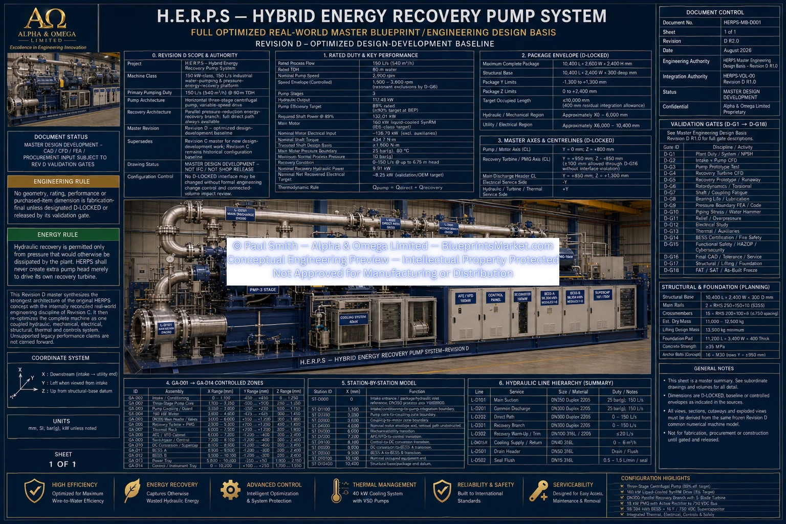
HERPS_MASTER_ENGINEERING_DESIGN_BASIS_REV_D_R2.0.webp
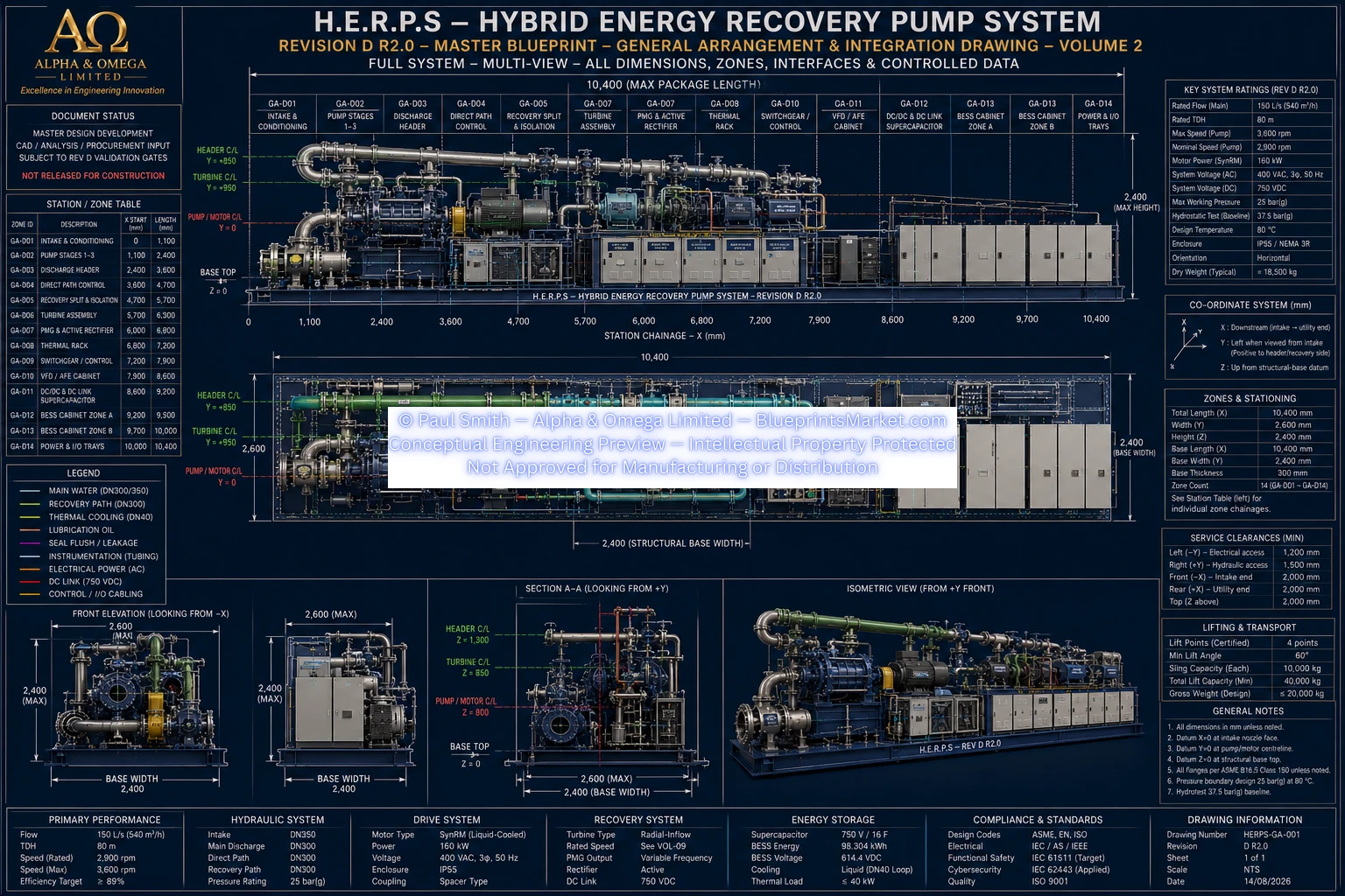
HERPS_MASTER_ENGINEERING_DESIGN_BASIS_REV-SHEET-1_D_R2.0.webp
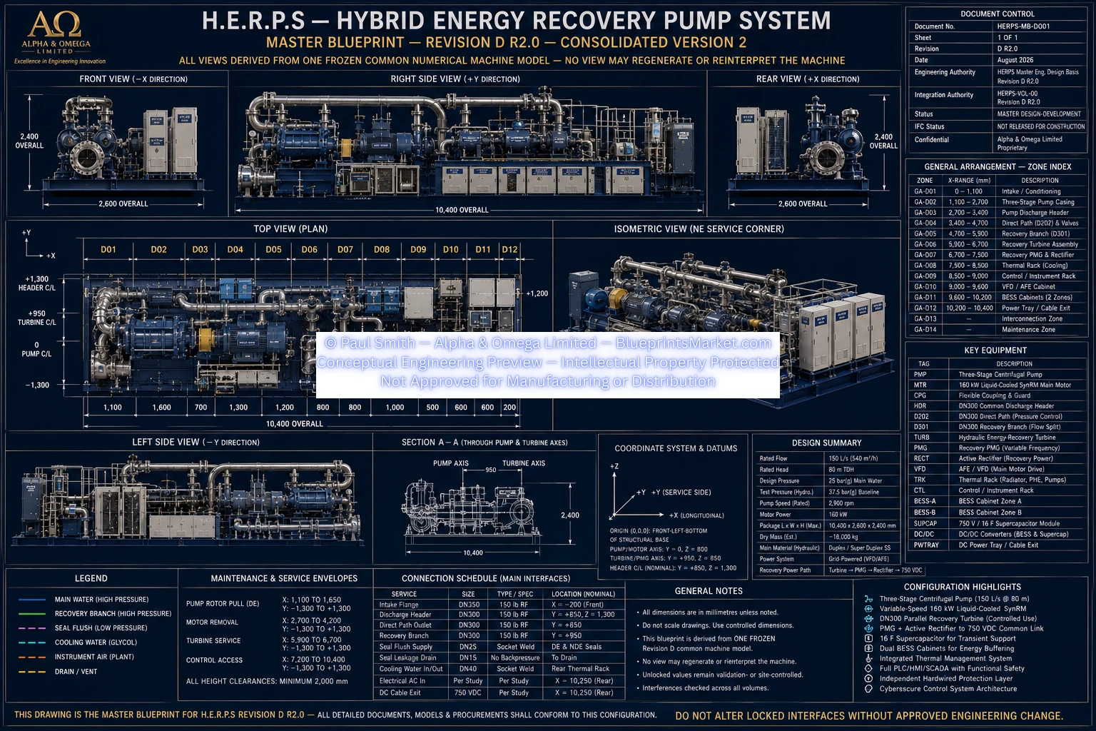
HERPS_MASTER_ENGINEERING_DESIGN_BASIS-SHEET-3_REV_D_R2.0.webp
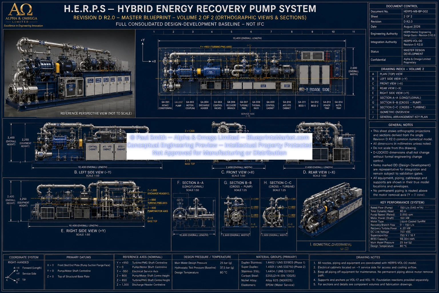
HERPS_MASTER_ENGINEERING_DESIGN_BASIS-SHEET-4_REV_D_R2.0.webp
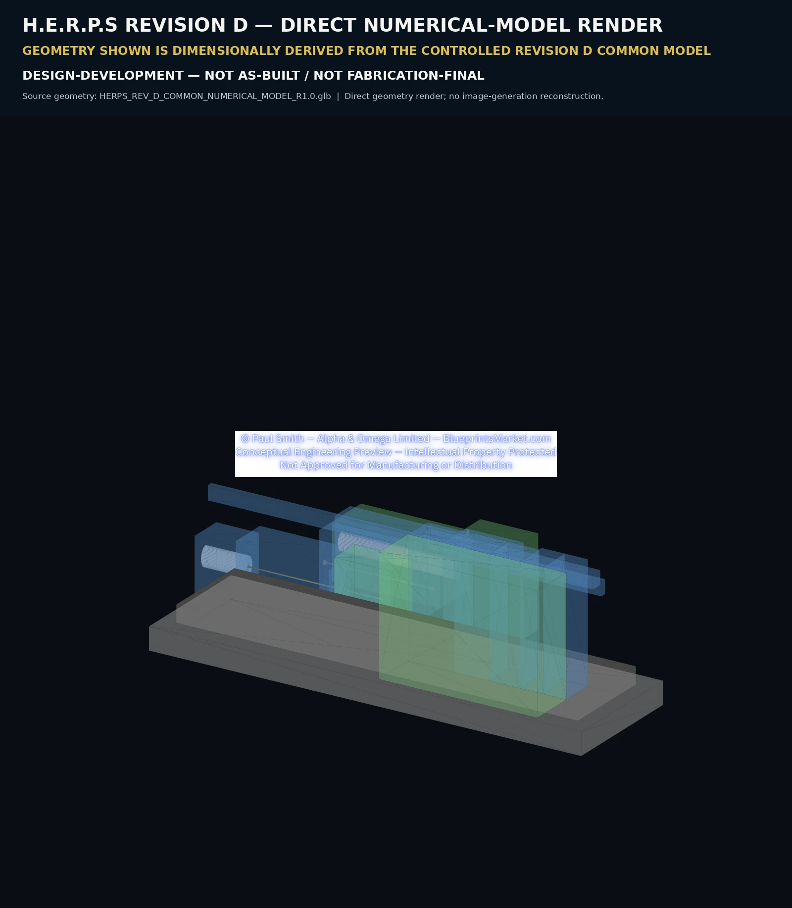
HERPS_REV_D_DIRECT_NUMERICAL_MODEL_RENDER_R1.0.webp
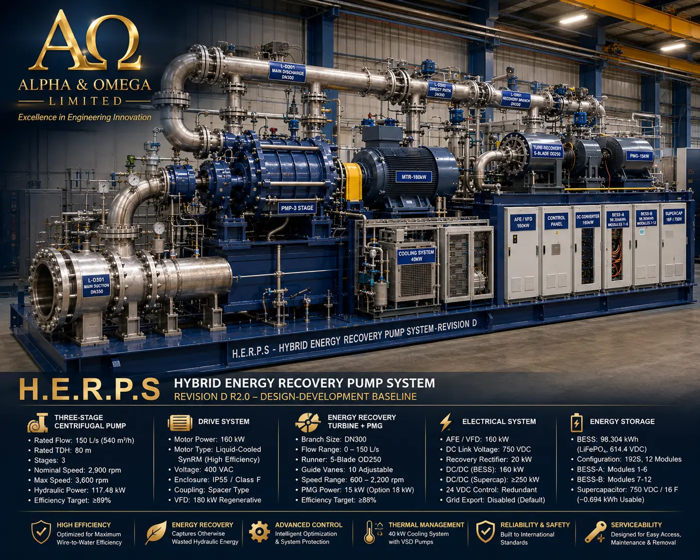
HERPS-3D-COVER.webp
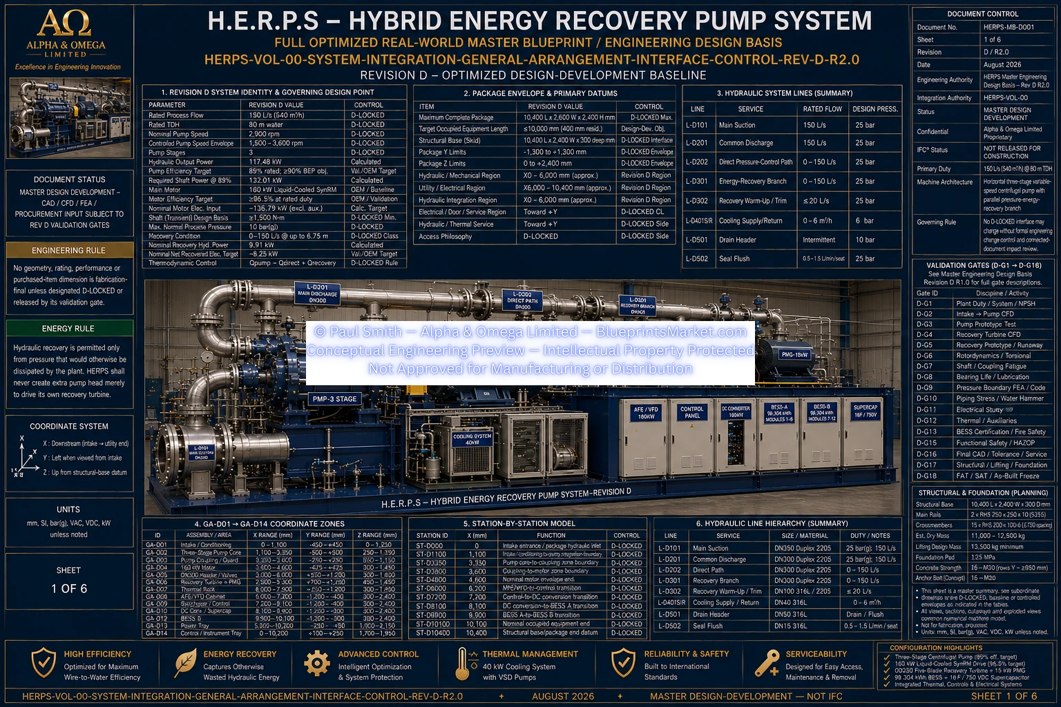
HERPS-VOL-00-SYSTEM-INTEGRATION-GENERAL-ARRANGEMENT-INTERFACE-CONTROL-REV-D-R2.0.webp
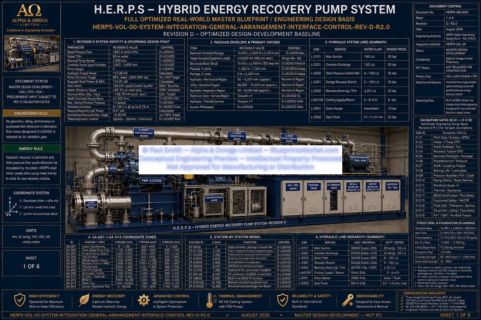
HERPS-VOL-00-SYSTEM-INTEGRATION-GENERAL-ARRANGEMENT-INTERFACE-CONTROL-SHEET-1-OF-6-REV-D-R2.0.webp
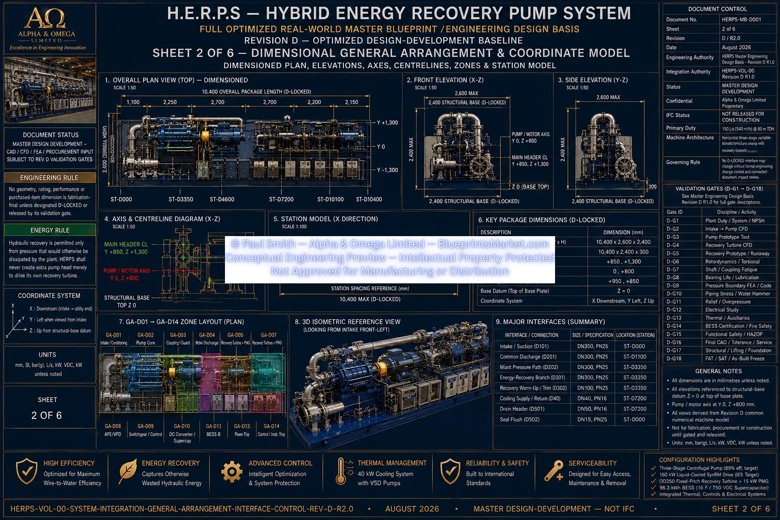
HERPS-VOL-00-SYSTEM-INTEGRATION-GENERAL-ARRANGEMENT-INTERFACE-CONTROL-SHEET-2-OF-6-REV-D-R2.0.webp
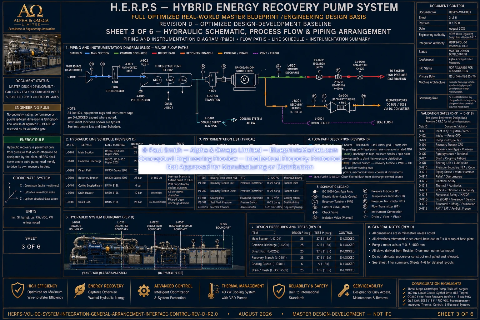
HERPS-VOL-00-SYSTEM-INTEGRATION-GENERAL-ARRANGEMENT-INTERFACE-CONTROL-SHEET-3-OF-6-REV-D-R2.0.webp
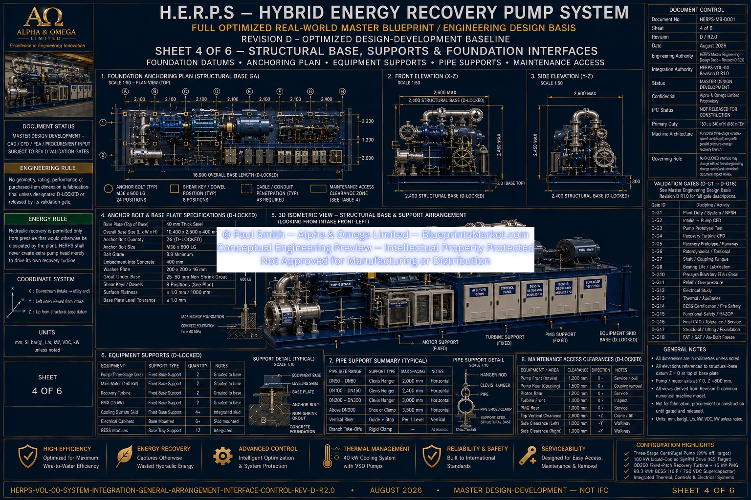
HERPS-VOL-00-SYSTEM-INTEGRATION-GENERAL-ARRANGEMENT-INTERFACE-CONTROL-SHEET-4-OF-6-REV-D-R2.0.webp
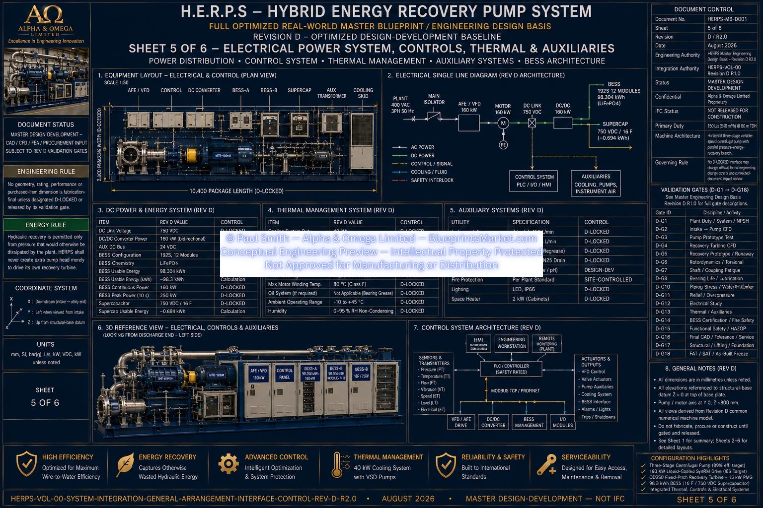
HERPS-VOL-00-SYSTEM-INTEGRATION-GENERAL-ARRANGEMENT-INTERFACE-CONTROL-SHEET-5-OF-6-REV-D-R2.0.webp
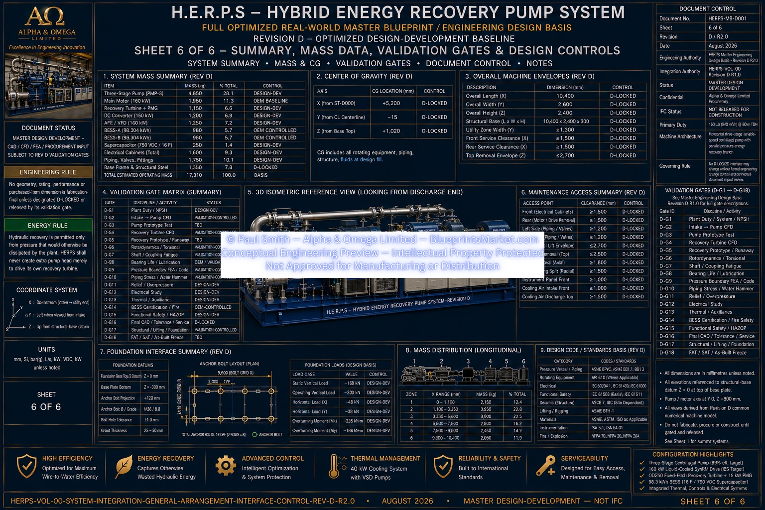
HERPS-VOL-00-SYSTEM-INTEGRATION-GENERAL-ARRANGEMENT-INTERFACE-CONTROL-SHEET-6-OF-6-REV-D-R2.0.webp