© Paul Smith — Alpha & Omega Limited — PlatformClouds.com — Conceptual Engineering Preview — Not Approved for Manufacturing
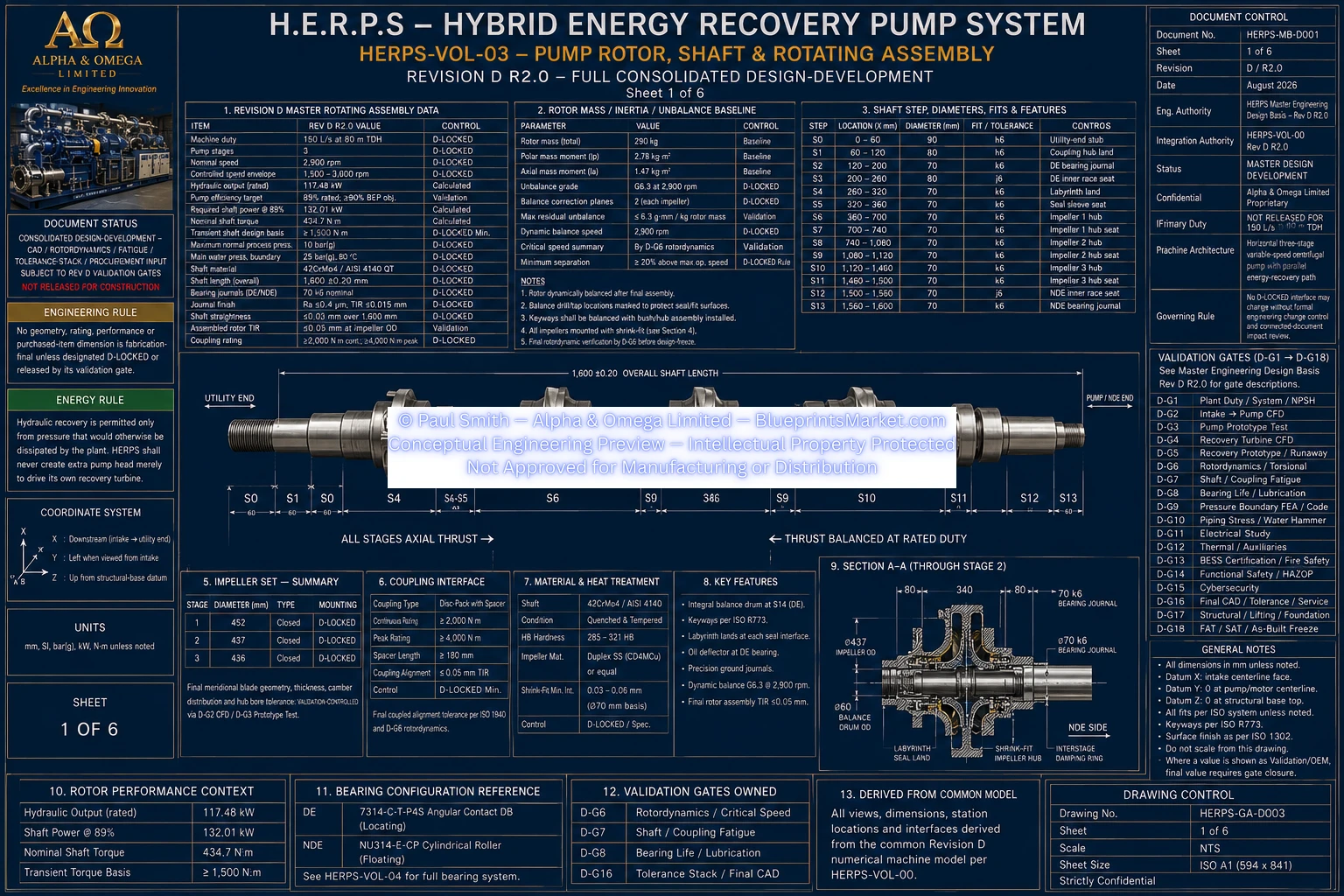
HERPS-VOL-03-PUMP-ROTOR-SHAFT-AND-ROTATING-ASSEMBLY-SHEET-1-OF-6-REV-D-R2.0.webp

H.E.R.P.S — HYBRID ENERGY RECOVERY PUMP SYSTEM
Revision D R2.0 — Pump Rotor, Shaft, Bearings, Housings & Lubrication
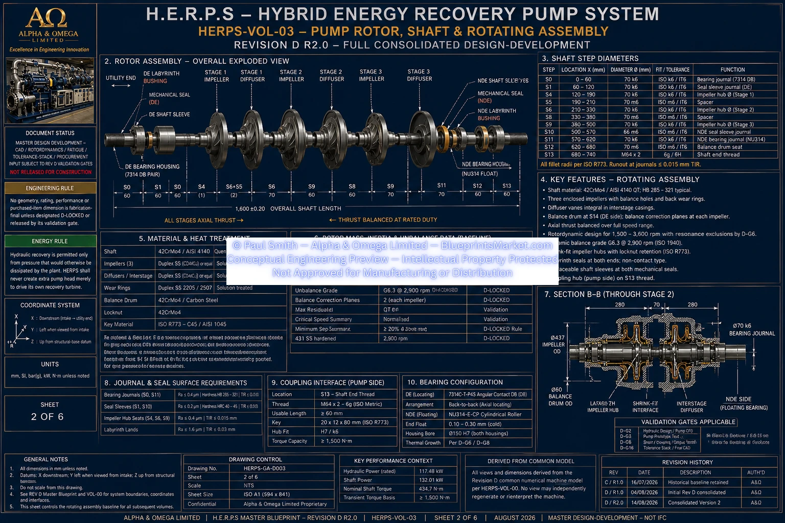
The H.E.R.P.S Revision D rotating assembly combines the 1,600 mm stepped pump shaft, three-stage rotor stack, coupling interface, drive-end locating bearing system, non-drive-end floating bearing, precision bearing housings, oil-bath lubrication, temperature monitoring and vibration monitoring into one coordinated rotating machinery architecture.
HERPS-VOL-03 defines the complete Revision D pump rotor, shaft and rotating-assembly baseline for the horizontal three-stage centrifugal pump. The shaft transmits torque from the main SynRM drive through the spacer coupling to the three pump impellers while simultaneously carrying hydraulic radial loads, residual axial thrust, rotor weight, coupling loads, residual unbalance and transient torsional loading.
42CrMo4 / AISI 4140 quenched-and-tempered steel or approved equivalent.
1,600 ±0.20 mm.
2,900 rpm.
1,500–3,600 rpm, subject to rotordynamic exclusion bands.
Approximately 434.7 N·m.
Minimum 1,500 N·m Revision D design basis.
Revision D establishes tightly controlled shaft and journal geometry so that the complete rotor remains compatible with the bearing, seal, impeller, coupling and casing interfaces.
| Feature | Revision D R2.0 Basis |
|---|---|
| Overall shaft length | 1,600 ±0.20 mm |
| Bearing journal diameter | 70 k6 nominal |
| Bearing journal finish | Ra ≤0.4 µm |
| Journal TIR | ≤0.015 mm |
| Shaft straightness | ≤0.03 mm over 1,600 mm |
| Assembled rotor TIR | ≤0.05 mm at impeller OD |
| Coupling seat | 75 h6 |
| Impeller seats | 80 h6 shaft interface / 80 H7 impeller bore |
| Seal-sleeve seats | 75 h6 |
| Balance-drum seat | 85 h6 baseline |
The rotating stack includes three impellers installed in the controlled Stage 1, Stage 2 and Stage 3 sequence on the Revision D stepped shaft. Each impeller retains an 80 H7 bore and a 95 mm axial envelope.
The current mechanical impeller outside-diameter envelope is approximately 290–310 mm, with the final hydraulic surface and exact operating geometry remaining controlled by the hydraulic CFD and prototype validation program.
Individual rotating components are controlled during manufacture and the assembled rotor is dynamically balanced to G2.5 or tighter where the Revision D rotordynamic validation requires.
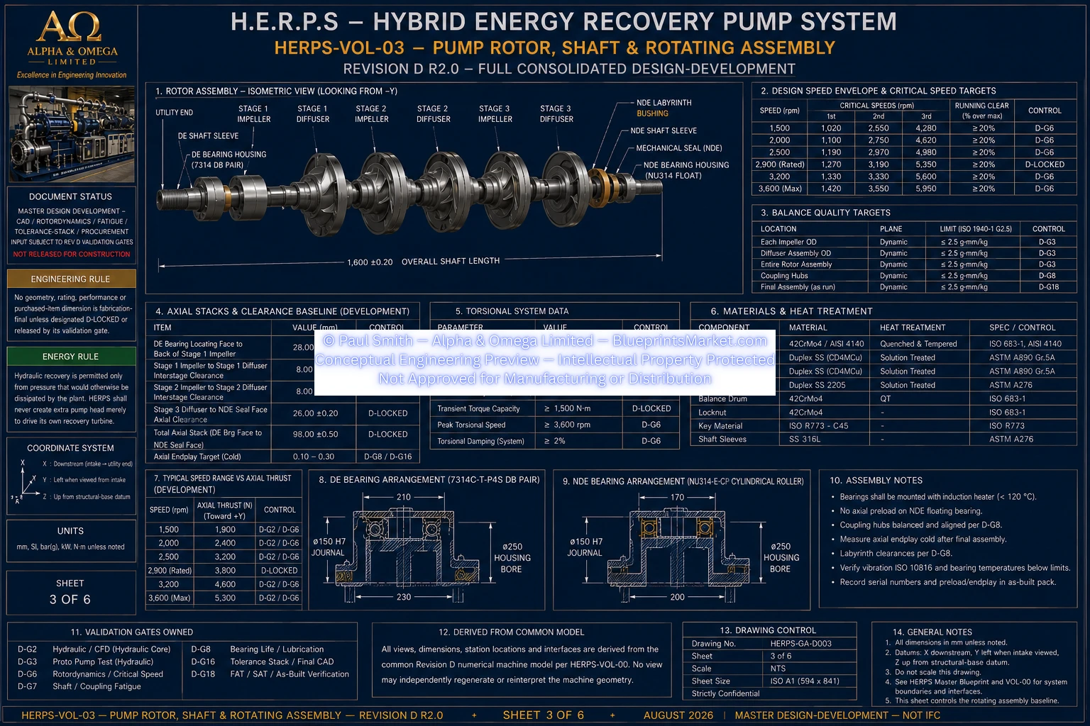
The complete bearing, shaft, coupling, impeller and support model is evaluated over the released 1,500–3,600 rpm operating envelope. Any unacceptable critical-speed or resonance regions identified by validation are excluded from continuous operation through the variable-frequency-drive control system.
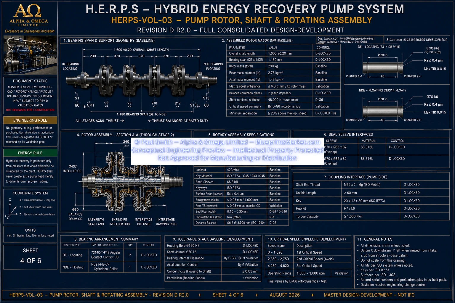
HERPS-VOL-04 retains a two-support bearing arrangement consisting of a drive-end locating pair and a non-drive-end floating cylindrical roller bearing.
Two 7314-class angular-contact bearings arranged as a back-to-back locating pair.
Radial support, bidirectional residual thrust reaction and rotor axial datum.
One NU314-class cylindrical roller bearing.
Radial support with controlled axial freedom for thermal growth.
70 mm ID × 150 mm OD × 35 mm width per bearing.
150 H7 development-controlled bearing interface.
The three-stage hydraulic assembly generates axial thrust that is partially counteracted by the balance-drum system. The resulting residual axial thrust is carried by the drive-end back-to-back angular-contact bearing pair.
The non-drive-end cylindrical roller bearing remains a true floating radial support and is not used as a second fixed axial location. This allows differential shaft growth to occur without generating unintended thermal thrust.
The steady-state axial movement target at the locating-bearing system is ≤0.15 mm after thermal stabilization, while the NDE bearing accommodates the required differential growth.
| Feature | Drive End | Non-Drive End |
|---|---|---|
| Housing envelope | 320 × 300 × 310 mm | 280 × 300 × 310 mm |
| Housing bore | 150 H7 | 150 H7 |
| Effective oil volume | 3.5 L baseline | 2.5 L baseline |
| Oil-level indication | Centreline-level bulls-eye sight glass | Bulls-eye sight glass |
| Constant-level oiler | Provided | Not mandatory |
| Temperature channels | Two Pt100 channels | One Pt100 channel |
| Vibration monitoring | X / Y | X / Y |
| Local removal clearance | ≥400 mm | ≥400 mm |
Both bearing housings use an oil-bath lubrication architecture. ISO VG46 is the Revision D development baseline, with the final viscosity grade and selected lubricant remaining subject to bearing OEM and bearing-life validation.
Oil bath at both DE and NDE bearings.
ISO VG46.
Constant-level oiler plus visible sight glass.
Visible sight glass.
Filtered or desiccant/filtered breather arrangement where required by the service environment.
Magnetic drain at each bearing housing.
Dedicated oil-condition sampling point preferred at each housing.
Each bearing housing interfaces with the rotating shaft through an approximately Ø80 mm labyrinth interface. The Revision D radial development-clearance baseline is 0.25–0.35 mm.
Final labyrinth clearance remains validation-controlled against shaft runout, bearing movement, thermal growth, rotor deflection and manufacturing tolerance stack so that no rubbing occurs throughout the released operating range.
Revision D integrates dedicated temperature and vibration monitoring directly into the bearing architecture.
Three Pt100 channels total — two at the DE locating pair and one at the NDE floating bearing.
Four orthogonal channels total — DE X/Y and NDE X/Y.
FAT vibration signatures are retained as condition-monitoring baselines for service comparison.
Insulated-bearing and/or shaft-grounding strategy applied where the VFD common-mode assessment requires it.
Controlled through fatigue analysis, optimized shoulder blends, NDE, transient-torque design basis and released locking geometry.
Controlled through Revision D rotordynamic analysis and VFD exclusion bands.
Controlled through released hydraulic loads, preload/endplay, internal clearance and bearing-life validation.
Prevented by maintaining the NDE bearing as a true floating cylindrical-roller support.
Controlled through oil-bath lubrication, DE constant-level oiler, sight glasses and commissioning checks.
Controlled through clearance, runout, thermal and deflection validation.
Controlled through VFD common-mode assessment and the released bearing-current mitigation strategy.
Controlled through individual rotating-component balancing and final complete-rotor dynamic balancing.
Revision D R2.0 establishes the coordinated shaft, rotor and bearing design-development baseline, but final bearing preload, endplay, internal clearance, L10 bearing life, selected lubricant product, bearing-current mitigation hardware, final locking details and rotordynamic exclusion bands remain controlled by their applicable OEM and Revision D validation gates.
These values are not represented as fabrication-final until the required hydraulic load, rotordynamic, fatigue, bearing-life, electrical common-mode, tolerance-stack and FAT/SAT validations are complete.
Consolidated Design-Development — Not IFC — Not Approved for Manufacturing.
HERPS-VOL-03-PUMP-ROTOR-SHAFT-AND-ROTATING-ASSEMBLY-SHEET-1-OF-6-REV-D-R2.0.webp
HERPS-VOL-03-PUMP-ROTOR-SHAFT-AND-ROTATING-ASSEMBLY-SHEET-2-OF-6-REV-D-R2.0.webp
HERPS-VOL-03-PUMP-ROTOR-SHAFT-AND-ROTATING-ASSEMBLY-SHEET-3-OF-6-REV-D-R2.0.webp
HERPS-VOL-03-PUMP-ROTOR-SHAFT-AND-ROTATING-ASSEMBLY-SHEET-4-OF-6-REV-D-R2.0.webp
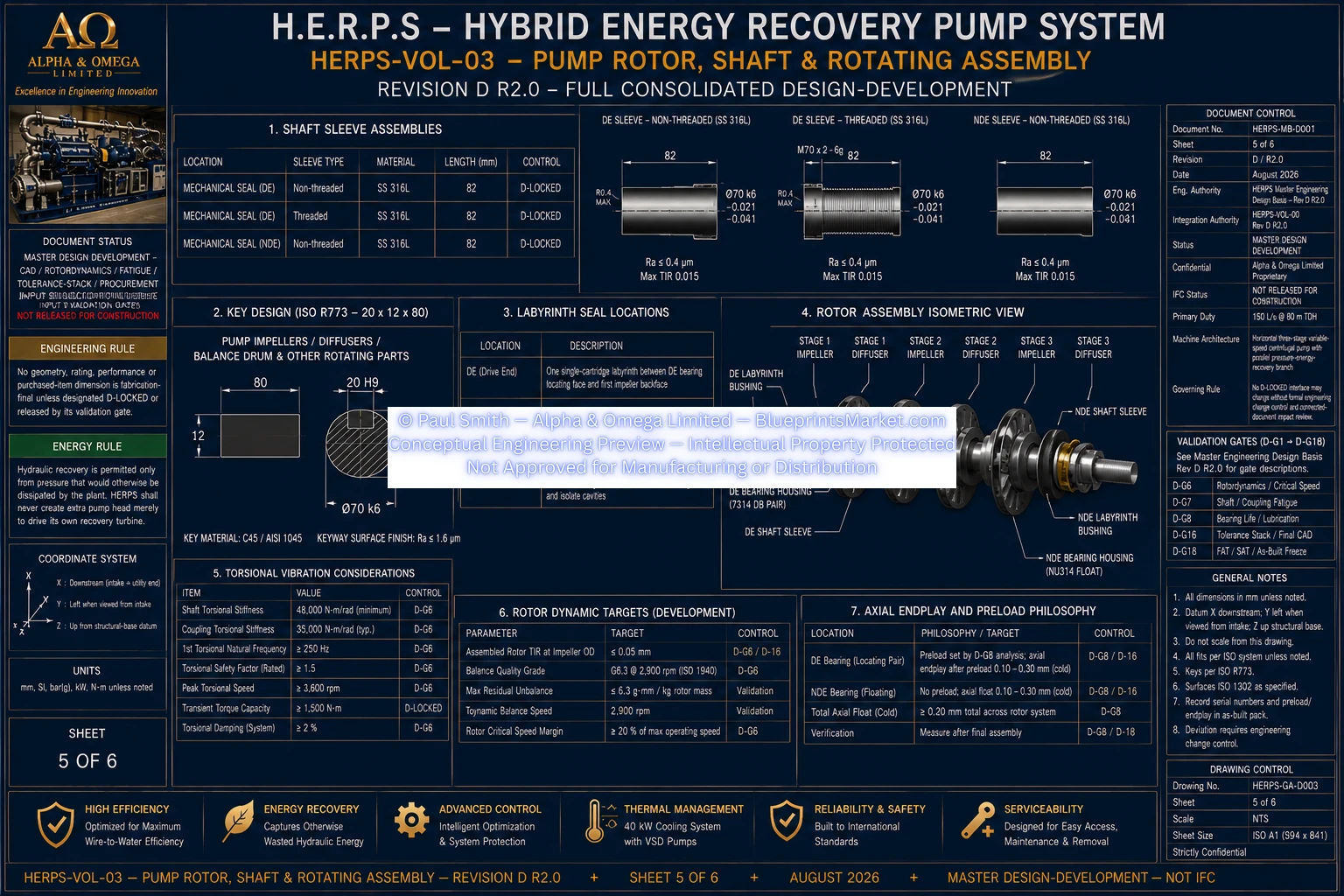
HERPS-VOL-03-PUMP-ROTOR-SHAFT-AND-ROTATING-ASSEMBLY-SHEET-5-OF-6-REV-D-R2.0.webp
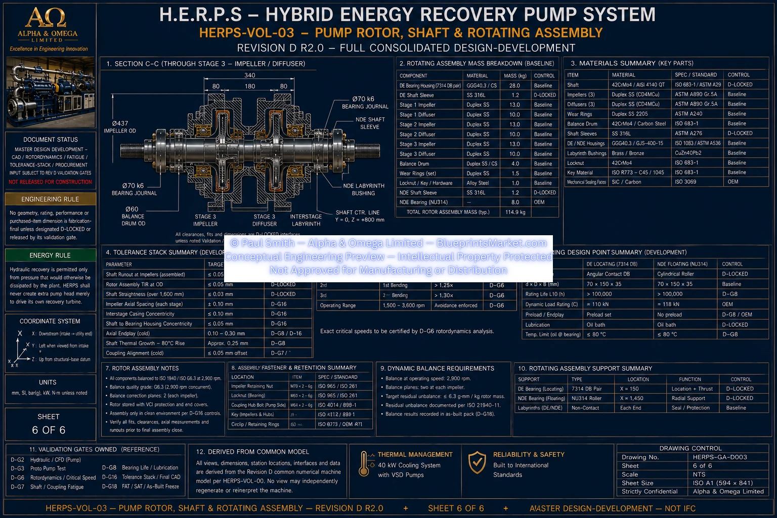
HERPS-VOL-03-PUMP-ROTOR-SHAFT-AND-ROTATING-ASSEMBLY-SHEET-6-OF-6-REV-D-R2.0.webp
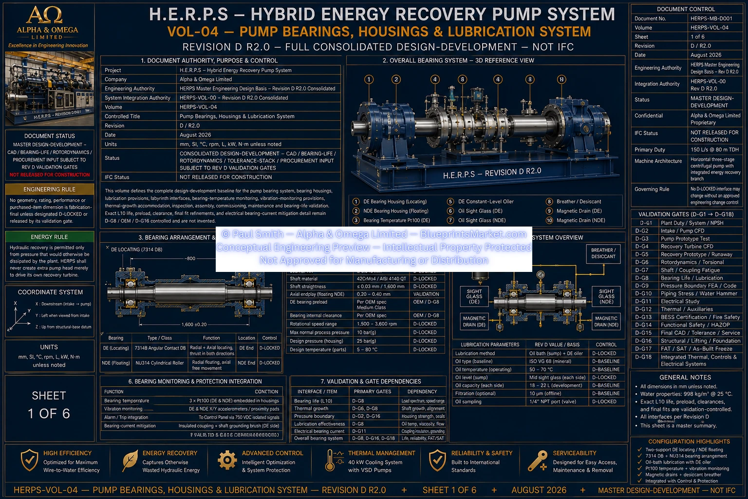
HERPS-VOL-04-PUMP-BEARINGS-HOUSINGS-AND-LUBRICATION-SYSTEM-SHEET-1-OF-6-REV-D-R2.0.webp
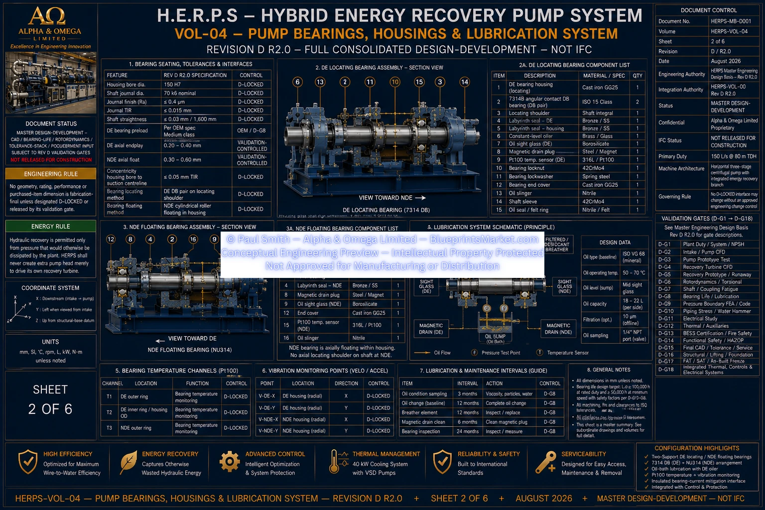
HERPS-VOL-04-PUMP-BEARINGS-HOUSINGS-AND-LUBRICATION-SYSTEM-SHEET-2-OF-6-REV-D-R2.0.webp
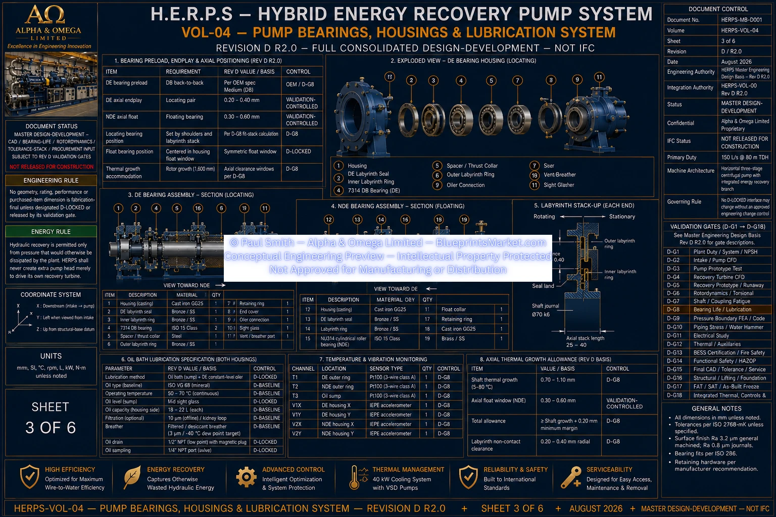
HERPS-VOL-04-PUMP-BEARINGS-HOUSINGS-AND-LUBRICATION-SYSTEM-SHEET-3-OF-6-REV-D-R2.0.webp
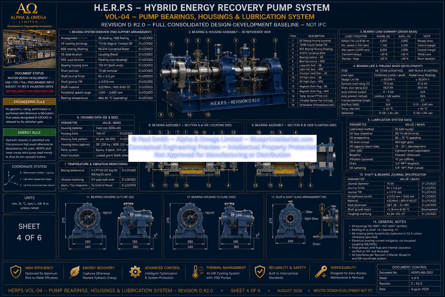
HERPS-VOL-04-PUMP-BEARINGS-HOUSINGS-AND-LUBRICATION-SYSTEM-SHEET-4-OF-6-REV-D-R2.0.webp
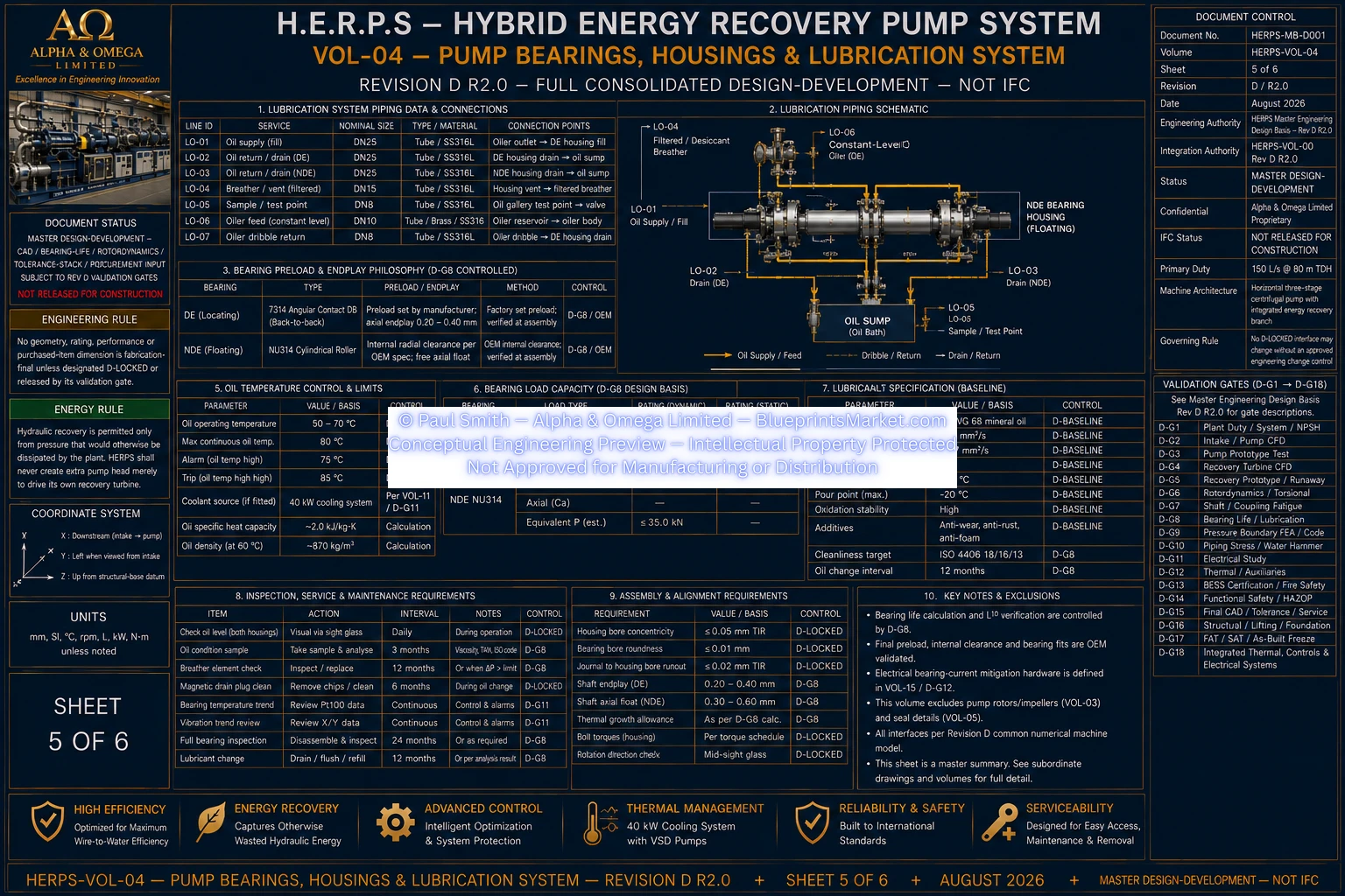
HERPS-VOL-04-PUMP-BEARINGS-HOUSINGS-AND-LUBRICATION-SYSTEM-SHEET-5-OF-6-REV-D-R2.0.webp
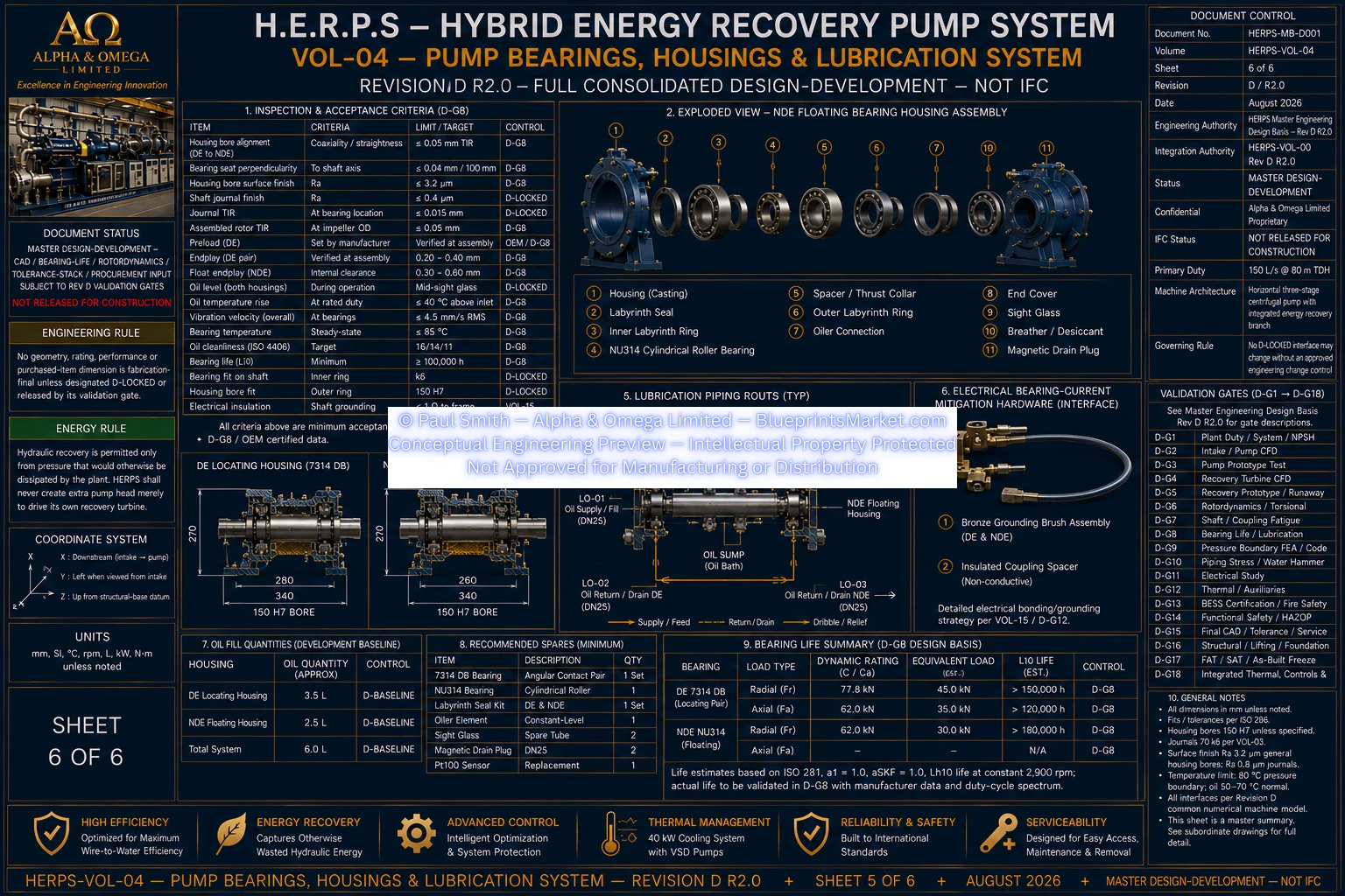
HERPS-VOL-04-PUMP-BEARINGS-HOUSINGS-AND-LUBRICATION-SYSTEM-SHEET-6-OF-6-REV-D-R2.0.webp