© Paul Smith — Alpha & Omega Limited — PlatformClouds.com —
Conceptual Engineering Preview — Not Approved for Manufacturing
HERPS-VOL-2-THREE-STAGE-CENTRIFUGAL-PUMP-HYDRAULIC-CORE-SHEET-1-OF-6_REV_D_R2.0.webp

H.E.R.P.S — HYBRID ENERGY RECOVERY PUMP SYSTEM
HERPS-VOL-02 — Revision D R2.0
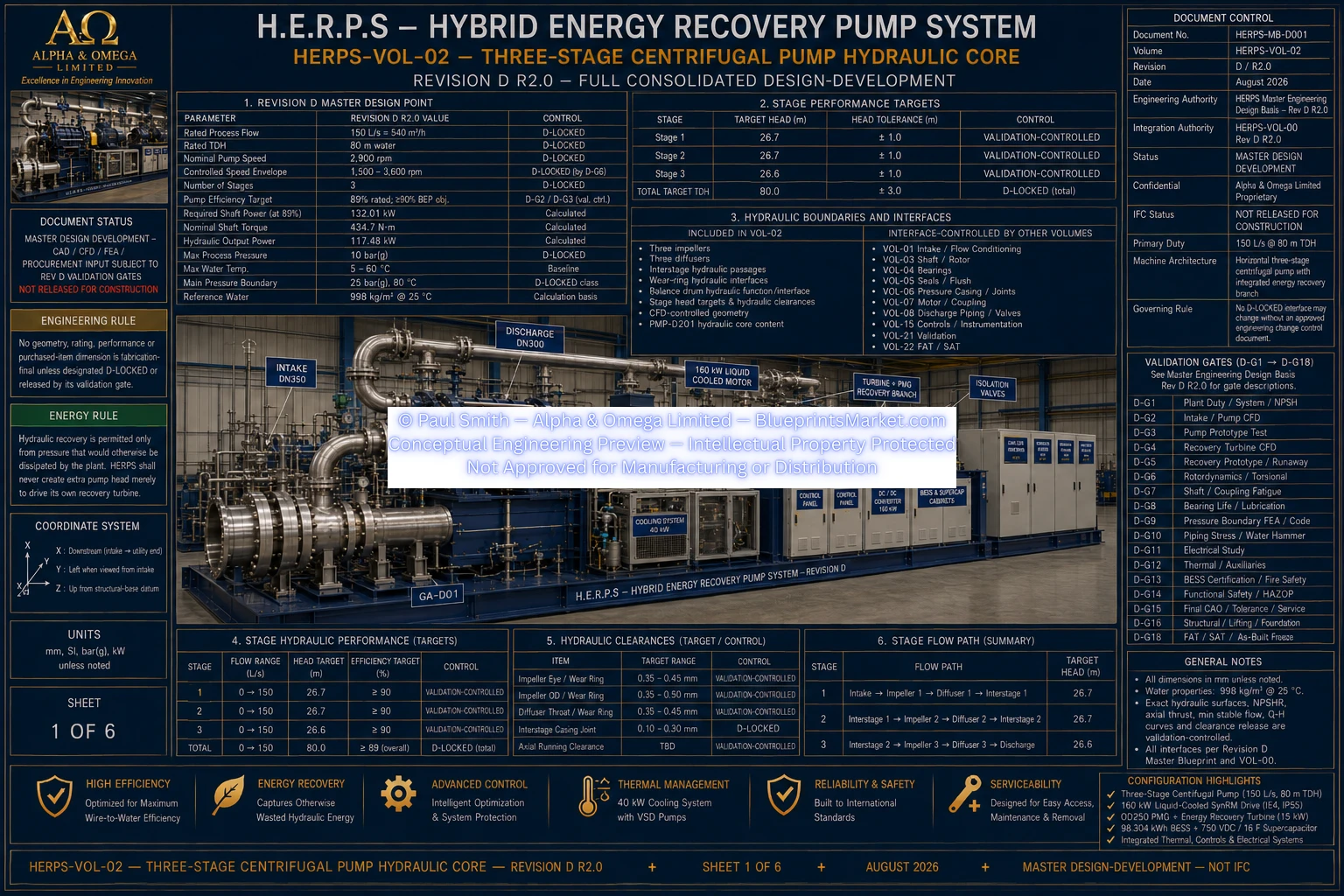
The H.E.R.P.S Revision D hydraulic core is a horizontal three-stage centrifugal pumping assembly developed around a rated process flow of 150 L/s at 80 m total dynamic head and a nominal pump speed of 2,900 rpm.
The hydraulic core incorporates three Super Duplex 2507 impellers, three Duplex 2205 diffuser assemblies, interstage hydraulic transfer passages, wear-ring hydraulic interfaces and the balance-drum hydraulic function required to manage the three-stage pump flow path.
150 L/s — 540 m³/h.
80 m water.
3.
2,900 rpm.
1,500–3,600 rpm, subject to prohibited rotordynamic resonant bands.
117.48 kW at the rated design point.
89% at rated duty, with a ≥90% BEP development objective subject to validation.
132.01 kW at 89% pump efficiency.
Maximum 10 bar(g).
25 bar(g) at 80 °C design class.
Conditioned DN350 suction flow enters the Stage 1 impeller coaxially on the H.E.R.P.S pump shaft centreline.
| Stage | Revision D Head Target |
|---|---|
| Stage 1 | 26.7 m |
| Stage 2 | 26.7 m |
| Stage 3 | 26.6 m |
| Total | 80.0 m TDH |
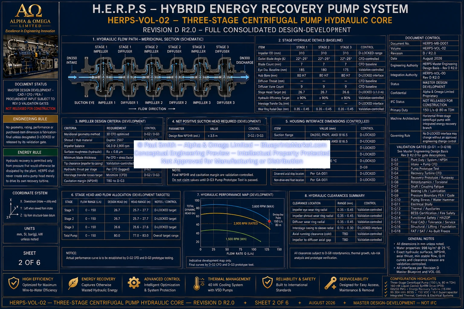
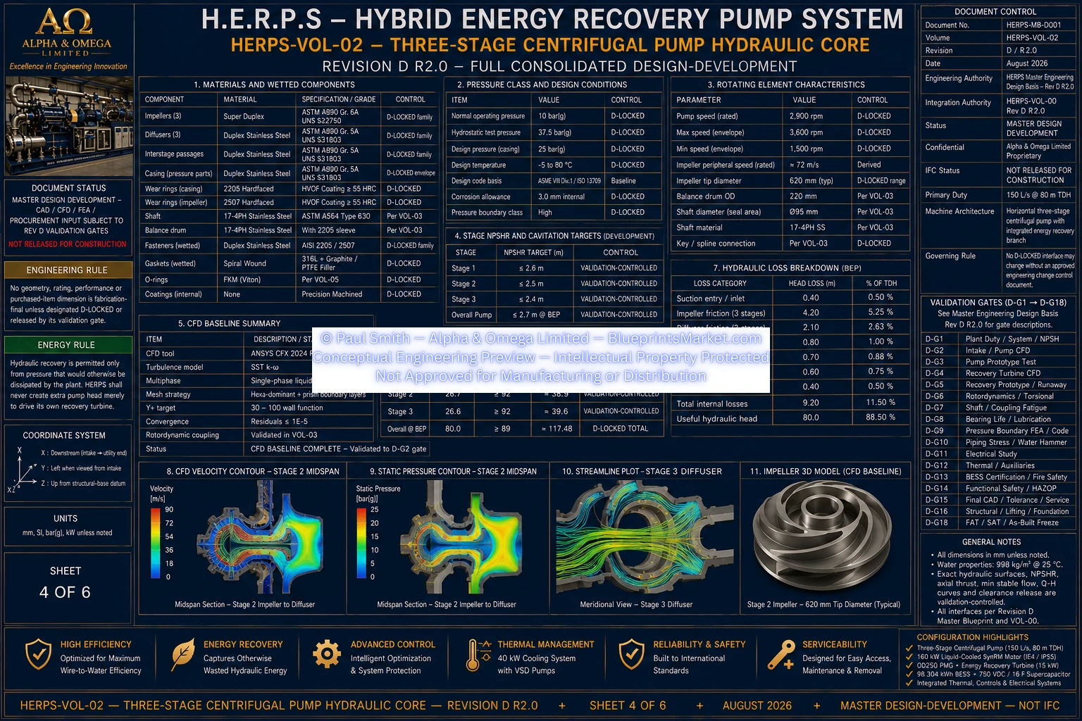
The Revision D hydraulic core uses three Super Duplex 2507 impellers with controlled mechanical envelopes suitable for the coordinated three-stage pump stack.
| Feature | Revision D Baseline |
|---|---|
| Quantity | 3 |
| Material Family | Super Duplex 2507 |
| OD Development Envelope | 290–310 mm |
| Nominal CFD Target | Approximately 300 mm |
| Axial Width | 95 mm |
| Bore | 80 H7 |
| Stage 1 Eye Baseline | 185 mm |
| Stage 2 Eye Baseline | 180 mm |
| Stage 3 Eye Baseline | 175 mm |
| Stage 1 b2 Baseline | 32 mm |
| Stage 2 b2 Baseline | 30 mm |
| Stage 3 b2 Baseline | 28 mm |
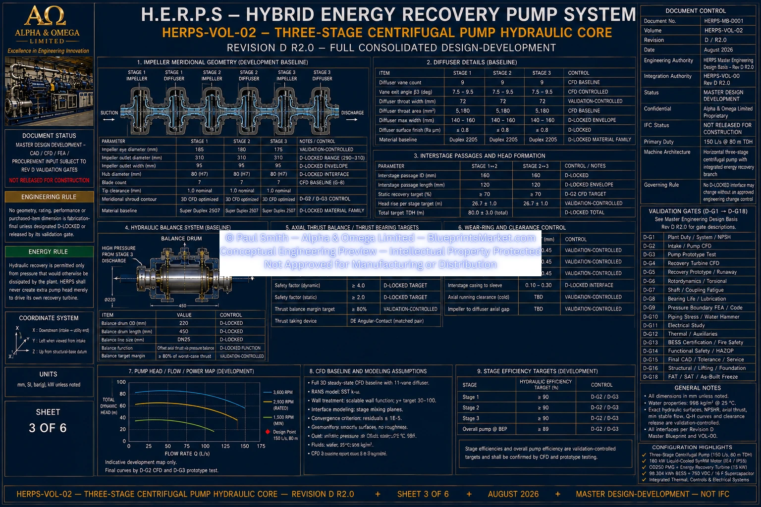
Each pump stage is followed by a Duplex 2205 diffuser assembly. The diffuser system converts the high-velocity flow leaving each impeller into pressure while guiding the water into the subsequent interstage transfer path.
3 diffuser assemblies.
Duplex 2205.
430 mm.
9 vanes with an 8–11 vane sensitivity range used during hydraulic development.
The Revision D wear-ring interface uses a hardfaced Super Duplex 2507 / Duplex 2205 material pairing.
The current design-development radial clearance target is 0.35–0.45 mm where validated by the hydraulic, thermal, rotordynamic and manufacturing-tolerance studies.
The Revision D hydraulic architecture retains the balance-drum function to reduce the axial thrust generated by the three-stage pump.
The development radial-clearance target is 0.20–0.30 mm, pending the released axial-thrust map and final connected rotor/bearing validation.
Volume 02 controls the hydraulic core but interfaces directly with the surrounding H.E.R.P.S mechanical and hydraulic volumes.
Conditioned DN350 suction flow from the Volume 01 intake and flow-conditioning assembly.
Shaft and rotating assembly controlled by Volume 03.
Bearing supports and lubrication controlled by Volume 04.
Mechanical seals and seal-flush system controlled by Volume 05.
Pressure boundary and casing architecture controlled by Volume 06.
Main motor and coupling controlled by Volume 07.
DN300 common discharge and hydraulic valve network controlled by Volume 08.
Volume 02 does not authorize invention of fabrication-final hydraulic surfaces. Exact impeller meridional surfaces, blade camber and thickness distribution, diffuser throat geometry, diffuser camber, NPSHR, minimum stable flow, axial hydraulic thrust, final hydraulic clearances and final pump performance curves remain subject to the applicable Revision D CFD and prototype validation gates.
The common numerical model and coordinated Revision D CAD stack govern geometric truth for hydraulic-core geometry.
HERPS-VOL-2-THREE-STAGE-CENTRIFUGAL-PUMP-HYDRAULIC-CORE-SHEET-1-OF-6_REV_D_R2.0.webp
HERPS-VOL-2-THREE-STAGE-CENTRIFUGAL-PUMP-HYDRAULIC-CORE-SHEET-2-OF-6_REV_D_R2.0.webp
HERPS-VOL-2-THREE-STAGE-CENTRIFUGAL-PUMP-HYDRAULIC-CORE-SHEET-3-OF-6_REV_D_R2.0.webp
HERPS-VOL-2-THREE-STAGE-CENTRIFUGAL-PUMP-HYDRAULIC-CORE-SHEET-4-OF-6_REV_D_R2.0.webp
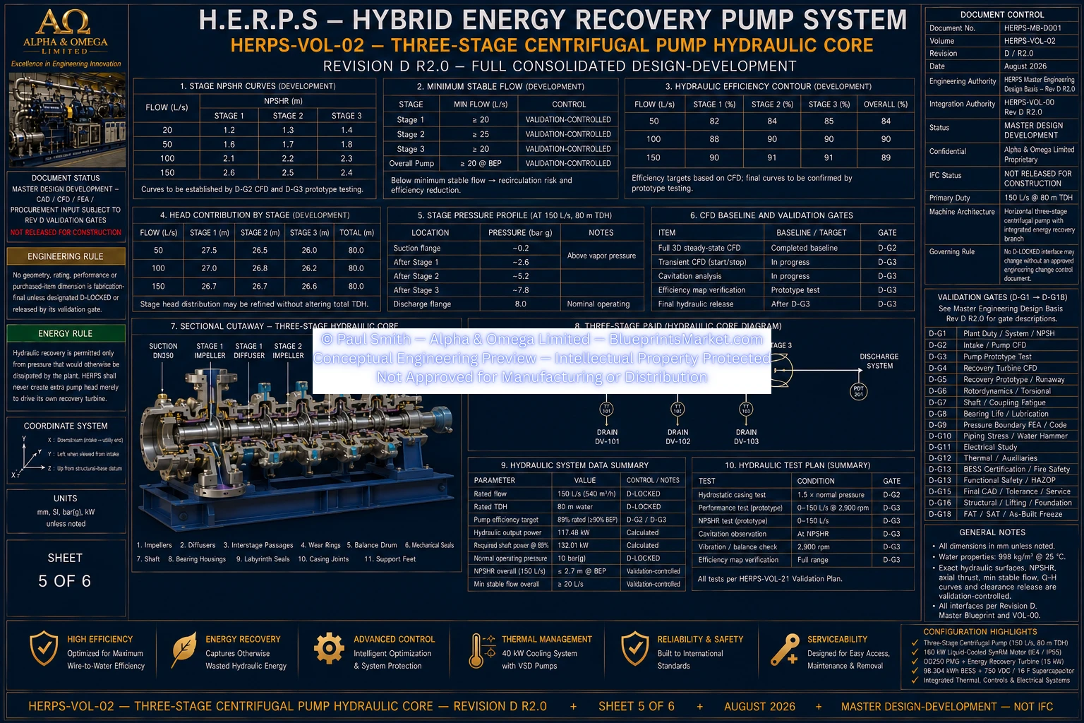
HERPS-VOL-2-THREE-STAGE-CENTRIFUGAL-PUMP-HYDRAULIC-CORE-SHEET-5-OF-6_REV_D_R2.0.webp

HERPS-VOL-2-THREE-STAGE-CENTRIFUGAL-PUMP-HYDRAULIC-CORE-SHEET-6-OF-6_REV_D_R2.0.webp
HERPS-VOL-02 Revision D R2.0 is the full consolidated design-development hydraulic-core baseline for new Revision D work. It supersedes Revision C Volume 02 wherever the earlier configuration conflicts with the Revision D common model.
Final impeller and diffuser hydraulic surfaces, NPSHR, minimum continuous stable flow, axial thrust, hydraulic clearances and final Q-H, efficiency and power curves remain validation-controlled.
Consolidated Design-Development — Not IFC — Not Shop Release — Not As-Built — Not Approved for Manufacturing.