H.E.R.P.S — Installation, Commissioning & Operation Guide
Revision D R2.0 — Assembly • Installation • Alignment • FAT • SAT •
Commissioning • Operation • Safety
Public engineering overview of the controlled installation, commissioning
and operational lifecycle for the H.E.R.P.S Hybrid Energy Recovery Pump
System, from physical package assembly and site installation through
alignment, testing, startup, operating modes, shutdown and final acceptance.
Revision D Installation & Commissioning Framework
The H.E.R.P.S Revision D R2.0 installation and commissioning architecture
is organized as a controlled engineering sequence rather than a collection
of independent installation tasks.
The physical build progresses from structural skid preparation through
pump assembly, drive-system installation, hydraulic routing, recovery-train
integration, thermal equipment, electrical cabinets, BESS, instrumentation,
cabling, pressure testing, flushing, final alignment and pre-FAT completion.
The sequence is specifically arranged to reduce interface clashes,
inaccessible connections, nozzle strain, contamination and late-stage
alignment loss. :contentReference[oaicite:0]{index=0}
Machine Installation Baseline
| Parameter |
Revision D R2.0 Baseline |
| Machine Type |
Horizontal three-stage variable-speed centrifugal industrial
water pump with controlled hydraulic-energy-recovery path
|
| Rated Hydraulic Duty |
150 L/s at 80 m TDH |
| Rated Pump Speed |
2,900 rpm |
| Main Drive |
160 kW-class liquid-cooled SynRM development baseline |
| Recovery Architecture |
Controlled parallel hydraulic energy-recovery path |
| Maximum Complete Package Envelope |
10,400 mm L × 2,600 mm W × 2,400 mm H |
| Structural Base |
10,400 mm L × 2,400 mm W × 300 mm deep baseline |
| Engineering Status |
Master Design-Development — Not IFC |
These package-level values form the coordinated Revision D installation
basis, while validation-controlled, OEM-controlled and site-controlled
details remain subject to their respective release gates. :contentReference[oaicite:1]{index=1}
Controlled Real-World Installation Sequence
Revision D divides the physical realization of the H.E.R.P.S package into
coordinated build and installation phases.
-
Engineering Release & Incoming Inspection —
confirm released documentation, traceable materials, approved
purchased equipment and controlled interfaces.
-
Structural Skid Preparation —
fabricate and inspect the structural base, equipment-support areas,
mounting interfaces and lifting provisions.
-
Pump Component Manufacturing & Inspection —
manufacture and inspect pressure parts and rotating components under
the applicable engineering and quality controls.
-
Pump Rotor & Casing Assembly —
assemble the primary rotating and hydraulic machine while maintaining
cleanliness, controlled fits, free rotation and inspection records.
-
Pump & Motor Installation —
mount the pump and SynRM drive and establish preliminary mechanical
alignment.
-
Main Hydraulic Piping —
install suction, common discharge and direct hydraulic process paths
using independently supported piping.
-
Recovery Train Installation —
install the hydraulic energy-recovery turbine, PMG and associated
controlled recovery branch.
-
Thermal Management Installation —
install cooling equipment, thermal rack components and the associated
closed-loop cooling circuit.
-
Electrical & Energy Storage Integration —
install electrical cabinets, power conversion, DC equipment, BESS,
supercapacitor systems and cable-routing infrastructure.
-
Instrumentation & Field Wiring —
install, terminate, identify and test field instrumentation, I/O and
associated control wiring.
-
Pressure Testing & Flushing —
verify pressure integrity, cleanliness and restoration of the
hydraulic and cooling systems.
-
Final Piping-Connected Alignment —
verify shaft alignment, soft foot, piping strain and final machine
condition after all permanent connections are complete.
-
Pre-FAT Release —
close or formally control outstanding punch-list items before factory
acceptance testing begins.
This phase structure is defined directly in the Revision D real-world build
sequence. :contentReference[oaicite:2]{index=2}
VOLUME 20 — ASSEMBLY / INSTALLATION / ALIGNMENT / REAL-WORLD BUILD SEQUENCE
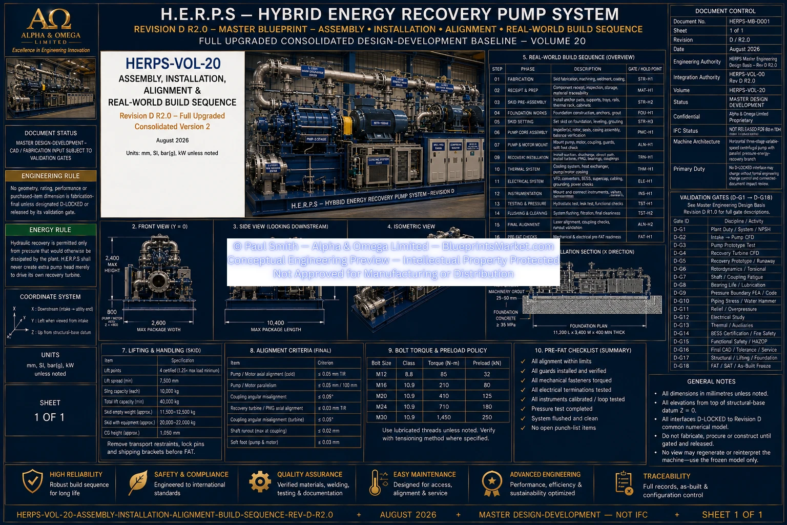
© Paul Smith — Alpha & Omega Limited — PlatformClouds.com —
Conceptual Engineering Preview — Not Approved for Manufacturing
HERPS-VOL-20-ASSEMBLY-INSTALLATION-ALIGNMENT-REAL-WORLD-BUILD-SEQUENCE-REV-D-R2.0.webp
Mechanical Alignment & Installation Integrity
Alignment is controlled throughout the installation process rather than
treated as a single final activity.
The pump and motor are initially mounted and aligned before permanent
process piping is fully connected. Final alignment is then checked again
after the hydraulic system is installed so that pipe strain, mounting
distortion or support loads cannot silently alter shaft alignment.
The Revision D pre-FAT checklist requires accepted preliminary and final
pump/motor alignment records, identification of the hot-growth basis,
correction of soft foot, independently supported DN350 suction and DN300
discharge/direct/recovery piping, acceptable nozzle strain and proven
equipment-removal corridors. :contentReference[oaicite:3]{index=3}
Pre-FAT Readiness
Factory testing does not begin simply because the package has been
physically assembled. Revision D requires a formal pre-FAT readiness
condition.
- Revision-controlled machine interfaces verified
- Vendor-certified equipment envelopes incorporated
- No unresolved physical clashes affecting release
- Pump and motor alignment records accepted
- Main hydraulic piping independently supported
- Pressure boundaries tested as required
- Hydraulic and cooling systems flushed and restored clean
- Power and control/instrument segregation verified
- Bonding, continuity and insulation checks completed
- Instrumentation calibrated and correctly tagged
- Trips, E-stops, permissives and fail states verified
- BESS and supercapacitor commissioning limited to approved procedures
- Open punch-list items formally categorized
Factory Acceptance Testing — FAT
FAT verifies the assembled H.E.R.P.S package at the factory or approved
test facility before shipment.
Acceptance is evidence-based: a design target, calculated result or CAD
value does not become an accepted machine result until it is verified by
the applicable test or inspection procedure. Test instruments are required
to have appropriate traceable calibration, and deviations or temporary
test configurations must be identified and dispositioned. :contentReference[oaicite:4]{index=4}
Principal FAT Activities
- Document and configuration verification
- Dimensional and as-built survey
- Mechanical inspection and free-rotation checks
- Hydrostatic and leak testing
- Electrical continuity, insulation and bonding checks
- Control I/O, permissive, trip and interlock simulation
- Cooling-loop functional testing
- No-load / low-load rotation and controlled speed testing
- Pump hydraulic performance verification
- Recovery turbine / PMG / rectifier testing
- BESS / DC conversion / supercapacitor / DC-link testing
- Integrated thermal and load testing
- Final protective-trip and controlled-shutdown testing
- Post-test inspection and NCR closure
- Signed FAT release when required records are complete
The Revision D FAT program explicitly covers hydraulic, rotating,
electrical, thermal, energy-storage, recovery and safety functions as one
integrated package. :contentReference[oaicite:5]{index=5}
VOLUME 22 — FAT / SAT / COMMISSIONING / PERFORMANCE ACCEPTANCE
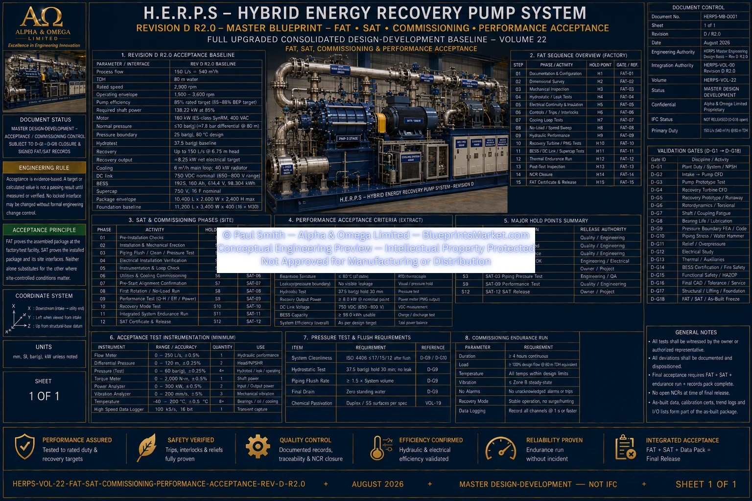
© Paul Smith — Alpha & Omega Limited — PlatformClouds.com —
Conceptual Engineering Preview — Not Approved for Manufacturing
HERPS-VOL-22-FAT-SAT-COMMISSIONING-PERFORMANCE-ACCEPTANCE-REV-D-R2.0.webp
Site Installation & SAT Preconditions
Passing FAT does not by itself establish site readiness. Site Acceptance
Testing verifies the installed package together with the actual site
interfaces.
- Approved site foundation, anchors and grout complete
- Foundation levels and anchor coordinates surveyed
- Electrical and process utilities available
- Actual protection settings installed and verified
- Plant suction conditions and downstream pressure profile confirmed
- Skid anchored and grouted
- Permanent piping independently supported
- No unacceptable nozzle strain
- Final piping-connected alignment completed
- BESS site safety interfaces approved
- LOTO, guarding, E-stops and safe access complete
- Approved commissioning plan and abort criteria issued
These are explicit SAT prerequisites in the Revision D acceptance
program. :contentReference[oaicite:6]{index=6}
Commissioning Philosophy
Commissioning progresses from safe static verification into controlled
dynamic operation. Systems are proven incrementally rather than placing the
complete machine immediately into full-load operation.
Mechanical, hydraulic, electrical, thermal, instrumentation, control and
protection functions must each demonstrate readiness before the machine is
advanced to higher-energy operating states.
FAT establishes the factory package condition, while SAT and commissioning
confirm actual installation interfaces and operating behaviour. Neither
replaces the other where site-dependent conditions govern machine
performance or safety. :contentReference[oaicite:7]{index=7}
Normal Grid-Fed Startup Sequence
The Revision D operating architecture requires startup permissives to be
healthy before motor torque is enabled.
- Confirm operating mode and authorized operator control.
-
Verify that maintenance lockouts and equipment-isolation conditions
permit startup.
-
Verify emergency-stop loops, independent protective trips and critical
sensor health.
-
Start and prove required thermal-management operation.
-
Verify suction-path availability and establish the direct discharge
path.
-
Confirm switchgear and AFE/VFD readiness, including the approved
precharge sequence.
-
Keep hydraulic energy recovery disabled or bypassed during initial
acceleration unless a validated automatic startup sequence specifically
permits otherwise.
-
Accelerate the SynRM-driven pump through the validated speed ramp.
-
Establish stable process flow and pressure.
-
Transition to the selected automatic flow-control or pressure-control
mode.
-
Enable energy recovery only after hydraulic conditions, direct-path
fallback capability and PMG/DC-link readiness are proven.
-
Enable BESS support functions only when BMS and associated conversion
systems report valid readiness.
The Revision D system specifically requires the direct hydraulic process
path to be available and treats energy recovery as a secondary function,
not a prerequisite for normal pump startup. :contentReference[oaicite:8]{index=8}
H.E.R.P.S Operating Modes
| Mode |
Primary Function |
| OFF / Isolated |
No commanded operation. Lockout/tagout and verified stored-energy
isolation govern.
|
| Standby |
Pump stopped while required controls, alarms and safety functions
remain available.
|
| Manual Commissioning |
Authorized local testing and setup with active permissives and
controlled bypass management.
|
| Automatic Flow Control |
Main VFD regulates pump operation to the required process-flow
target.
|
| Automatic Pressure Control |
Pump speed and hydraulic controls coordinate to maintain the
required plant-pressure target.
|
| Energy Recovery |
Recovery turbine and PMG operate only within available hydraulic
head while the direct path remains capable of takeover.
|
| Battery Peak Shaving |
BESS provides controlled transient input-demand support within
its approved SOC, thermal and electrical limits.
|
| Ride-Through |
BESS and supercapacitor systems provide finite-duration DC-link
support within validated limits.
|
| Emergency Shutdown |
Independent hardwired safety response overrides normal
PLC/HMI/SCADA and remote commands.
|
These modes and their safety constraints are defined by the Revision D
functional-safety architecture. :contentReference[oaicite:9]{index=9}
PLC, HMI, SCADA & Operator Interface
The H.E.R.P.S control architecture integrates the PLC, local HMI, SCADA
interfaces, instrumentation and field I/O while keeping independent
safety-critical protection separate from normal supervisory control.
The HMI provides machine overview, operating-mode selection, alarms,
trends, diagnostics and maintenance information. Normal operator screens
do not provide casual editing of safety-critical trip thresholds, and loss
of the HMI does not defeat independent protection or healthy automatic
machine control. :contentReference[oaicite:10]{index=10}
VOLUME 15 — PLC / HMI / SCADA / INSTRUMENTATION / FIELD I/O
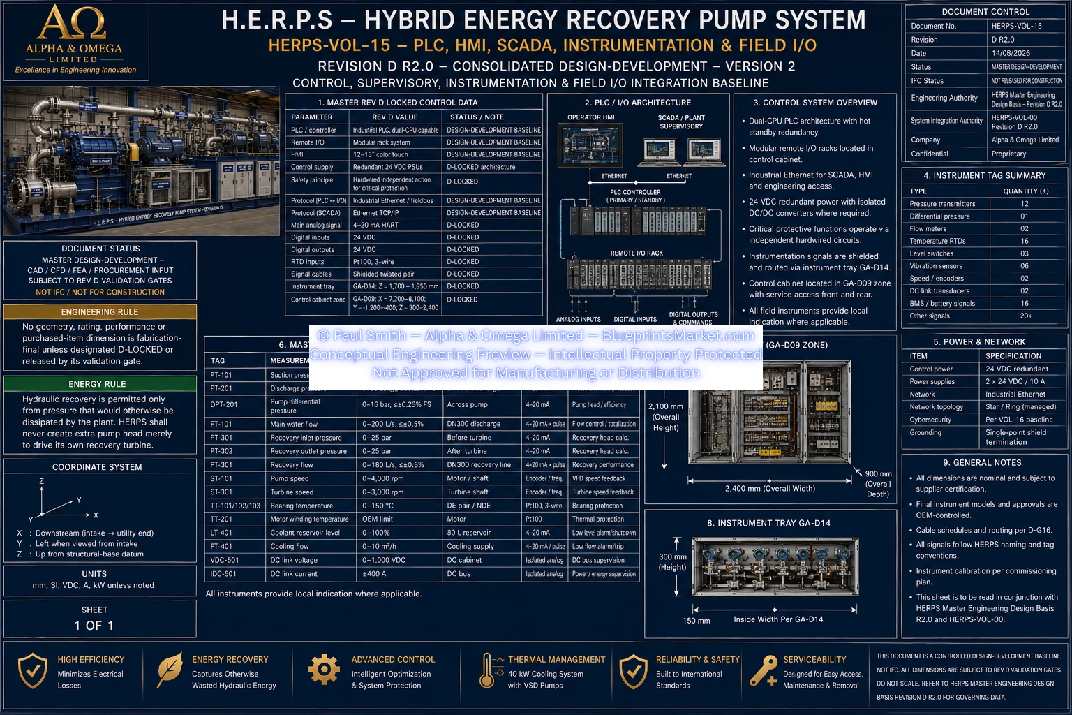
© Paul Smith — Alpha & Omega Limited — PlatformClouds.com —
Conceptual Engineering Preview — Not Approved for Manufacturing
HERPS-VOL-15-PLC-HMI-SCADA-INSTRUMENTATION-AND-FIELD-IO-REV-D-R2.0.webp
Energy-Recovery Operation
Energy recovery is enabled only when measured hydraulic conditions show
that genuine recoverable pressure head exists.
The system maintains the hydraulic conservation relationship:
Qpump =
Qdirect +
Qrecovery
The recovery branch cannot be commanded above measured pump flow, and the
direct hydraulic path assumes the required process duty if the turbine,
PMG, rectifier or recovery controls become unavailable.
:contentReference[oaicite:11]{index=11}
H.E.R.P.S therefore remains an externally powered pumping system with
energy recovery from otherwise-wasted hydraulic pressure reduction; the
recovery system does not create additional pump head merely to generate
electrical output.
Normal Stop & Controlled Shutdown
A normal shutdown transfers the system away from recovery operation before
the primary pump is brought to rest.
- Reduce or disable hydraulic-energy recovery.
- Transfer required process duty to the direct hydraulic path.
- Ramp pump torque and speed down through the controlled VFD sequence.
- Maintain required cooling for the validated post-run period.
- Return the package to standby.
A controlled protective trip similarly prioritizes recovery disablement and
process-safe direct-path operation where practical before the controlled
motor rundown occurs.
Emergency Shutdown & Independent Protection
Emergency shutdown is not dependent solely on ordinary PLC or SCADA logic.
Revision D uses independent hardwired protective actions layered over the
normal control system. :contentReference[oaicite:12]{index=12}
The emergency-stop architecture removes or inhibits torque-producing
outputs, commands the recovery subsystem toward its safe condition,
preserves or establishes the required direct hydraulic path and isolates
hazardous electrical energy as defined by the validated safety design.
Reset is deliberate and manual after the originating condition has been
cleared; resetting an E-stop does not itself restart the machine.
:contentReference[oaicite:13]{index=13}
VOLUME 16 — FUNCTIONAL SAFETY / HARDWIRED TRIPS / CONTROL MODES / CYBERSECURITY
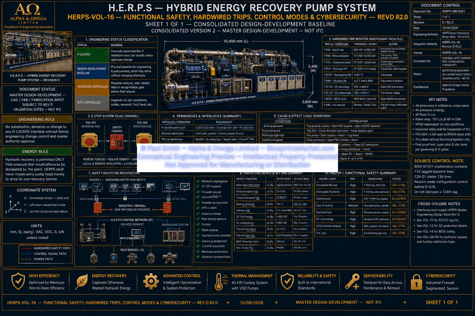
© Paul Smith — Alpha & Omega Limited — PlatformClouds.com —
Conceptual Engineering Preview — Not Approved for Manufacturing
HERPS-VOL-16-FUNCTIONAL-SAFETY-HARDWIRED-TRIPS-CONTROL-MODES-AND-CYBERSECURITY-REV-D-R2.0.webp
Integrated Operating & Endurance Verification
The FAT acceptance program includes integrated operation after the
individual subsystems have demonstrated readiness.
The machine is progressed through warm-up, controlled rated operation,
control-mode transitions, recovery operation, direct-path fallback,
energy-storage functions, normal stopping, standby and restart behaviour.
Acceptance requires the absence of unresolved leaks, overheating, abnormal
vibration, uncontrolled oscillation, hardware faults or unresolved
alarm/trip conditions during the defined test sequence.
:contentReference[oaicite:14]{index=14}
Commissioning Completion & Final Handover
Final release is based on documented objective evidence rather than design
expectation alone.
The Revision D handover process includes accepted FAT and SAT records,
commissioning logs, performance reports, punch-list and NCR disposition,
measured as-built configuration, controlled drawings, software and
configuration backups, calibration and test records, applicable
certificates, operation and maintenance information and final operating
release. :contentReference[oaicite:15]{index=15}
A machine does not become a frozen production/as-built configuration merely
because construction or testing has occurred. Revision D reserves final
acceptance for the applicable validation, FAT/SAT and measured as-built
release process. :contentReference[oaicite:16]{index=16}
Engineering Status
Revision: D R2.0
Primary Installation Authority:
HERPS-VOL-20 — Assembly, Installation, Alignment & Real-World Build Sequence
Commissioning & Acceptance Authority:
HERPS-VOL-22 — FAT, SAT, Commissioning & Performance Acceptance
Controls Authority:
HERPS-VOL-15 — PLC, HMI, SCADA, Instrumentation & Field I/O
Operational Safety Authority:
HERPS-VOL-16 — Functional Safety, Hardwired Trips, Control Modes & Cybersecurity
Status:
Master Design-Development — Not IFC / Not Approved for Manufacturing
Explore the H.E.R.P.S Revision D Engineering System
This page provides a public engineering overview of the H.E.R.P.S
installation, commissioning and operating architecture. Detailed
fabrication procedures, validation-controlled engineering, vendor-specific
settings, final site parameters and purchaser-controlled technical records
remain within the applicable engineering documentation and release process.
View the Main H.E.R.P.S Product Page
View Full System Integration
Contact Blueprints Market
for product and licensing enquiries.
© Paul Smith — Alpha & Omega Limited — PlatformClouds.com — Conceptual Engineering Preview — Not Approved for Manufacturing
HERPS-VOL-22-FAT-SAT-COMMISSIONING-PERFORMANCE-ACCEPTANCE-REV-D-R2.0.webp
© Paul Smith — Alpha & Omega Limited — PlatformClouds.com — Conceptual Engineering Preview — Not Approved for Manufacturing
HERPS-VOL-20-ASSEMBLY-INSTALLATION-ALIGNMENT-REAL-WORLD-BUILD-SEQUENCE-REV-D-R2.0.png.webp
