H.E.R.P.S — Materials, Fabrication, Welding, Surface Finish & Tolerances
HERPS-VOL-19 — Revision D R2.0
Hybrid Energy Recovery Pump System (H.E.R.P.S)
Revision D Manufacturing & Materials Baseline
HERPS-VOL-19 establishes the controlled design-development baseline for
materials of construction, fabrication practice, welding control, examination,
surface treatment, coatings, machining quality, dimensional tolerances,
bolted-joint preload, identification, segregation, cleanliness, preservation
and manufacturing records for the complete HERPS package.
The manufacturing specification preserves the locked hydraulic, mechanical,
electrical, structural, thermal and package interfaces established by the
wider HERPS Revision D engineering system.
Manufacturing Design Basis
| Parameter |
Revision D Baseline |
| Machine |
160 kW-drive-class horizontal three-stage variable-speed centrifugal industrial water pump with controlled hydraulic-energy-recovery path |
| Rated Duty |
150 L/s at 80 m TDH |
| Rated Pump Speed |
2,900 rpm |
| Main Water Pressure Boundary |
25 bar(g) design |
| Design Temperature |
80 °C |
| Hydrostatic Proof Baseline |
37.5 bar(g), subject to governing code and material factors |
| Package Envelope |
10,400 L × 2,600 W × 2,400 H mm maximum |
| Structural Base |
10,400 L × 2,400 W × 300 mm deep |
Revision D Materials Governance
Material substitution is not permitted solely on nominal strength equivalence.
Any substitution affecting corrosion resistance, weldability, heat treatment,
magnetic behavior, galvanic compatibility, fatigue, cavitation resistance,
pressure-code compliance, mass, thermal expansion, electrical bonding or
dimensional interfaces requires formal engineering review.
- Positive material identification and traceability for critical alloy components
- Material certificates retained for pressure, rotating, lifting and structural primary components
- Duplex, super-duplex and stainless materials protected from carbon-steel contamination
- Mixed-material interfaces reviewed for galvanic and crevice-corrosion risk
- Critical wetted fasteners maintained under controlled material traceability
Unified HERPS Material Schedule
| Component Family |
Revision D Material |
Manufacturing Function |
| Pump Casings / Main Wetted Pressure Parts |
Duplex Stainless Steel 2205 |
Primary corrosion-resistant pressure material |
| Impellers / Turbine Runner |
Super Duplex 2507 |
Cavitation and erosion-resistant rotating wetted components |
| Stage Diffusers / Interstage Casings |
Duplex 2205 |
Pressure and wetted fabrication |
| Turbine Housing / Guide-Vane Housing |
Duplex 2205 |
Pressure/wetted energy-recovery structure |
| Main Pump Shaft |
42CrMo4 / AISI 4140 Class, Quenched & Tempered |
≥700 MPa yield-strength basis |
| Turbine Shaft |
17-4PH / Protected 4140 |
Corrosion-protected rotating shaft route |
| Shaft Sleeves |
17-4PH or Super Duplex 2507 |
Replaceable wear/seal interfaces |
| Balance Drum |
17-4PH + 2205 Sleeve |
Axial-thrust management component |
| Mechanical Seal Faces |
SiC / SiC |
Mechanical sealing surfaces |
| Main Process Piping |
Duplex 2205 |
DN350 / DN300 / DN300 main-water network |
| Small-Bore Process / Instrumentation |
316L Stainless Steel |
Impulse, drain, flush and vent systems |
| Cooling System Wetted Components |
316L Stainless Steel |
Closed cooling loop |
| Skid / Frame / Supports |
S355 Structural Steel |
Primary structural support architecture |
| Wetted Fasteners |
A4-80 / Suitable Duplex |
Corrosion-compatible pressure/wetted fastening |
| Guards |
304 Stainless Steel |
1.5–2.0 mm typical sheet where specified |
Material Receipt, Traceability & Storage
- Verify purchase order, material grade, dimensions, heat/lot identity, certification and visible condition before fabrication.
- Transfer heat/lot traceability when parent material is cut.
- Segregate duplex, super-duplex, 316L and 304 stainless from carbon-steel contamination.
- Protect journals, bores, seal tracks and hydraulic surfaces from handling damage.
- Store elastomers and gaskets clean, dry and protected from UV, ozone and heat.
- Preserve electrical and BESS equipment according to supplier environmental and ESD requirements.
Duplex 2205 & Super Duplex 2507 Fabrication
Duplex and super-duplex fabrication uses qualified procedures intended to
preserve corrosion resistance, phase balance, toughness and pressure integrity
while preventing carbon-steel contamination.
- Qualified WPS/PQR required for pressure and wetted duplex welds
- Qualified welding personnel
- Controlled heat input and interpass temperature
- Matched or over-alloyed filler selected through the approved WPS
- Back purging where root oxidation would impair corrosion resistance or cleanliness
- Dedicated stainless tools, brushes and abrasives
- Carbon-steel wire brushes prohibited
- Arc strikes outside approved weld preparation prohibited
- Heat tint removed from wetted stainless/duplex surfaces
- Pickling/passivation or approved equivalent restoration where applicable
Carbon & Alloy Steel Fabrication
- S355 skid and frame fabricated to controlled structural drawings.
- Mounting datums are machine-finished after welding.
- Weld distortion is corrected before equipment alignment.
- 42CrMo4 / 4140 shafting is machined from Q&T stock meeting the specified strength basis.
- Uncontrolled weld repair on finished shafting is prohibited.
- 17-4PH heat-treatment condition is controlled by manufacturing drawing or vendor route.
- Structural weld sizes and NDE remain structural-calculation controlled.
Stainless Process Piping Fabrication
| Line |
Material / Size |
Service |
| L-101 Main Suction |
Duplex 2205 — 355.6 × 9.5 mm |
DN350, 25 bar main suction |
| L-201 / L-202 Discharge / Direct |
Duplex 2205 — 323.9 × 10.0 mm |
DN300, 25 bar |
| L-D301 Energy-Recovery Branch |
Duplex 2205 — DN300 |
25 bar, 0–150 L/s recovery path |
| L-302 Trim / Bypass |
316L / 2205 — 114.3 × 6.0 mm |
DN100 |
| L-401S/R Cooling |
316L — 48.3 × 3.7 mm |
DN40, 6 bar closed loop |
| L-501 Drain |
316L — 60.3 × 3.9 mm |
DN50 drain system |
| L-502 Seal Flush |
316L — 21.3 × 2.8 mm |
DN15, 25 bar |
Weld Category & Quality-Level Matrix
| Category |
Application |
Minimum Control |
| W1 — Pressure Boundary Critical |
Pump casings, pressure heads, DN350/DN300 process welds and turbine pressure housing |
Qualified WPS/PQR, qualified welder, full VT and required surface/volumetric examination |
| W2 — Wetted Non-Primary / Small Bore |
316L flush, drain, cooling and instrumentation connections |
Qualified procedure, VT and appropriate leak/pressure test |
| W3 — Rotating-Component Repair |
Impeller, runner or shaft repair only where specifically engineered |
No weld repair by default; engineering disposition required |
| W4 — Primary Structural |
Main rails, crossmembers, lifting lugs, anchor pads and major supports |
Approved structural WPS, VT and additional examination where required |
| W5 — Secondary Structural / Guards |
Guard frames, tray brackets and noncritical supports |
Controlled workmanship and visual examination |
Weld Joint Preparation & Execution
- Joint preparations must be clean, dry and accurately fitted.
- Oil, paint, scale and embedded iron contamination are prohibited in weld preparations.
- Root gaps, bevel angles, backing and purge arrangements follow approved WPS and fabrication drawings.
- Weld sequencing controls distortion of casing faces, skid datums, piping and rotating-equipment interfaces.
- Dedicated grinding media are required for stainless and duplex materials.
- Pressure-boundary weld repairs are documented, traceable and re-examined.
NDE & Examination Baseline
| Examination |
Revision D Application |
| VT — Visual Testing |
100% pressure-boundary and structural weld baseline workmanship examination |
| PT — Liquid Penetrant |
Critical duplex pressure-weld surfaces and relevant stainless areas |
| UT / RT |
Pressure-boundary welds as determined by category, geometry and governing code |
| MT |
Carbon/alloy structural or lifting welds where required |
| Dimensional Inspection |
Locked interfaces, shaft features, casing joints, datums, flanges and package envelope |
| PMI |
Critical alloy identity verification where required by the quality plan |
Pressure Testing, Leak Testing & Cleanliness
- Pressure-boundary NDE and dimensional release completed before hydrostatic testing.
- Main-water hydrostatic proof baseline: 37.5 bar(g), subject to governing code and material factors.
- Zero visible pressure-boundary leakage.
- Cooling loop pressure/leak testing follows the approved 6 bar-class procedure and purchased-equipment limits.
- Seal-flush lines are flushed and cleaned before final seal connection.
- Standing water is drained where storage or corrosion risk exists.
- No slag, abrasive, swarf, scale, wire, rags, loose fasteners or foreign material remains in completed systems.
Pickling, Passivation & Stainless Surface Restoration
- Heat tint and contamination removed after duplex welding.
- Pickling/passivation or approved equivalent restoration applied where appropriate.
- Chemical-treatment residues removed and neutralized or rinsed as required.
- Passivation is not used to conceal weld defects, embedded iron or inadequate preparation.
- Finished stainless and duplex surfaces remain protected from later carbon-steel contamination and coating overspray.
S355 Carbon-Steel Coating System
| Layer / Control |
Revision D Baseline |
| Substrate |
S355 skid, frame and structural supports |
| Preparation |
Blast-cleaned to approved coating specification |
| Primer |
Zinc-rich epoxy primer |
| Intermediate |
High-build epoxy |
| Topcoat |
Polyurethane |
| Total DFT |
250–350 µm baseline |
Machined Surface Finish Requirements
| Feature |
Revision D Requirement |
| Pump Shaft Journals |
Ra ≤ 0.4 µm |
| Seal Track / Sleeve |
Ra ≤ 0.4 µm |
| Fatigue-Critical Shaft Fillets |
Ra ≤ 1.6 µm; polished transitions |
| General Machined Surfaces |
Ra ≤ 1.6 µm unless function requires otherwise |
| Non-Machined Pressure Surface |
Ra ≤ 6.3 µm or applicable manufacturing standard |
| Casing Joint Faces |
Flatness ≤ 0.05 mm per 300 mm; ≤ 0.15 mm total |
| Flange Faces |
Flatness ≤ 0.15 mm |
| Base Mounting Pads |
Flatness ≤ 0.10 mm across each foot set |
| Motor / Pump Skid Datums |
Coplanarity before shims ≤ 0.25 mm |
Dimensional & Geometric Tolerances
| Feature |
Tolerance / Limit |
| Machined Dimensions ≤500 mm |
±0.10 mm unless fit stated |
| Machined Dimensions >500–2,000 mm |
±0.20 mm |
| Fabricated Skid Overall |
±2.0 mm |
| Pump Shaft Total Length |
1,600 ±0.20 mm |
| Shaft Straightness |
≤0.03 mm over 1,600 mm |
| Journal TIR |
≤0.015 mm |
| Assembled Rotor TIR at Impeller OD |
≤0.05 mm |
| Impeller Axial Runout |
≤0.03 mm |
| Impeller Bore |
80 H7 |
| Shaft Impeller Seats |
80 h6 |
| DE / NDE Bearing Journals |
70 k6 |
| Final Shaft Alignment |
Parallel ≤0.05 mm; angular ≤0.05° with hot-growth correction |
| Rotor Balance |
G2.5 or better, subject to final validation release |
Rotating-Component Manufacturing Quality
- Impellers and turbine runner preserve locked OD and bore envelopes.
- Final blade, meridional and camber surfaces remain CFD/prototype controlled.
- Individual impellers are balanced before complete rotor balancing.
- Assembled pump rotor balance baseline is G2.5 or better.
- No uncontrolled material removal is permitted after final dynamic balancing.
- Keyways, shoulders and fillets must remain free from burrs, laps and stress-raising damage.
- Bearing journals and seal tracks remain protected during assembly and shipping.
Bolted Joint, Torque & Preload Policy
HERPS does not apply a universal torque value across the machine. Controlled
joints use joint-specific tightening requirements based on fastener material,
lubrication, gasket condition, coating, washers and required clamp load.
- M30 casing through-studs use A4-80 or suitable duplex fasteners.
- Motor hold-down baseline uses four M30 fasteners on machined rails.
- Pump feet use two M24 slots per foot.
- Foundation interface carries a 16 × M30 concept anchor baseline.
- Purchased valves and flange joints use the applicable vendor torque requirements.
- Critical stainless fasteners use service-compatible anti-galling practice.
Galvanic Isolation & Mixed-Metal Interfaces
- Duplex 2205 to coated S355 interfaces use isolation where galvanic or crevice risk exists.
- Stainless piping uses compatible clamps or liners at carbon-steel supports.
- A4-80 and duplex fasteners in carbon structures require coating/isolation review.
- Copper electrical conductors use listed bonding hardware while preserving corrosion protection.
- Aluminium and composite equipment uses vendor-approved transition hardware where required.
Permanent Identification & Traceability
- Valves, instruments, rotating equipment and cabinets use permanent engraved or laser-marked stainless tags.
- Critical identification is not adhesive-only.
- Pressure-part heat and lot traceability is retained.
- Main flow paths receive permanent flow-direction identification where required.
- Electrical and BESS hazards receive the applicable permanent warning labels.
- Asset tag identity matches P&IDs, single-line diagrams, BOMs, instrument indexes and as-built records.
Hose, Tubing, Cable & Conduit Segregation
- Main power and VFD motor cables use dedicated power routing.
- DC-link, BESS and supercapacitor circuits use dedicated HV routing.
- Control and instrumentation use separate control/instrument routing.
- Impulse and seal-flush tubing is routed away from hot surfaces, sharp edges, moving parts and HV terminations.
- Cooling piping is not routed over unprotected electrical cabinets or BESS service openings where leakage could create a hazard.
- Final numerical EMC separation remains electrical-study and vendor controlled.
System Cleanliness Requirements
- Main hydraulic path flushed free of weld slag, scale, abrasive, swarf and foreign material.
- Seal-flush system maintains high particulate cleanliness downstream of its 50 µm replaceable filter.
- Bearing lubrication systems remain clean and dry.
- Cooling loop is flushed before final connection to heat-producing equipment.
- Instrument impulse lines are cleaned and protected from contamination.
- Electrical cabinets remain free of swarf, loose wire strands, liquids and conductive debris.
- BESS cabinets remain under supplier-certified contamination controls.
Fabrication Dimensional Control & Datum Transfer
Manufacturing inspection references the Revision D machine coordinate system:
X downstream along the machine, Y left when viewed from the intake, and Z upward
from the skid datum.
| Locked Interface |
Coordinate |
| Pump / Motor Shaft Centreline |
Y = 0 / Z = +800 mm |
| Turbine / Generator Shaft Centreline |
Y = +950 / Z = +850 mm |
Manufacturing Hold & Witness Points
- H1 — Material receipt and traceability
- H2 — Duplex WPS/PQR and welder qualification
- H3 — Pressure-weld completion before surface treatment
- H4 — Pressure-part dimensional inspection
- H5 — Shaft and rotor machining
- H6 — Rotor balance certification
- H7 — Skid weld completion before machining/coating
- H8 — Skid datum machining
- H9 — Coating completion
- H10 — Hydrostatic and leak testing
- H11 — Final cleanliness and preservation
- H12 — Final as-built dimensional survey
Manufacturing Quality Data Book
- Material certificates and traceability maps
- Approved WPS/PQR documentation and personnel qualifications
- Weld maps, repair logs and NDE reports
- PMI records where required
- Machining inspection reports
- Rotor balance certificates
- Coating preparation and DFT records
- Pickling and passivation treatment records
- Bolt and preload records
- Pressure and leak-test records
- Flushing, cleanliness and preservation records
- Nonconformance and approved engineering disposition records
- Final as-built dimensions and configuration records
Validation-Controlled Manufacturing Requirements
Revision D deliberately does not falsely freeze manufacturing parameters that
require final code calculations, qualified procedures, vendor information,
structural analysis or site-specific engineering.
- Final duplex WPS heat-input, interpass and filler variables
- Exact pressure-weld NDE percentages and acceptance classes
- Final casing wall and nozzle-reinforcement calculations
- Final structural and lifting-lug weld sizes
- Final valve and flange drilling/face requirements
- Joint-specific final torque values
- Severe-environment final coating specification
- Final electrical cable and conduit separation distances
- Supplier-certified BESS cell and module construction materials
Revision D Engineering Status
HERPS-VOL-19 Revision D R2.0 is a consolidated master design-development
manufacturing baseline. It provides coordinated CAD and fabrication input while
retaining the validation gates required before IFC, shop or final production release.
Final qualified welding variables, code-specific examination requirements,
structural weld sizing, purchased-component dimensions, joint preload values,
site coating requirements and other validation-controlled values remain subject
to their governing engineering release processes.
Explore the Complete H.E.R.P.S Revision D System
Materials, Fabrication, Welding, Surface Finish & Tolerances forms part of the
complete H.E.R.P.S Revision D multi-volume conceptual engineering blueprint system.
View the Complete HERPS System
Contact Blueprints Market for product, licensing
and engineering-package enquiries.
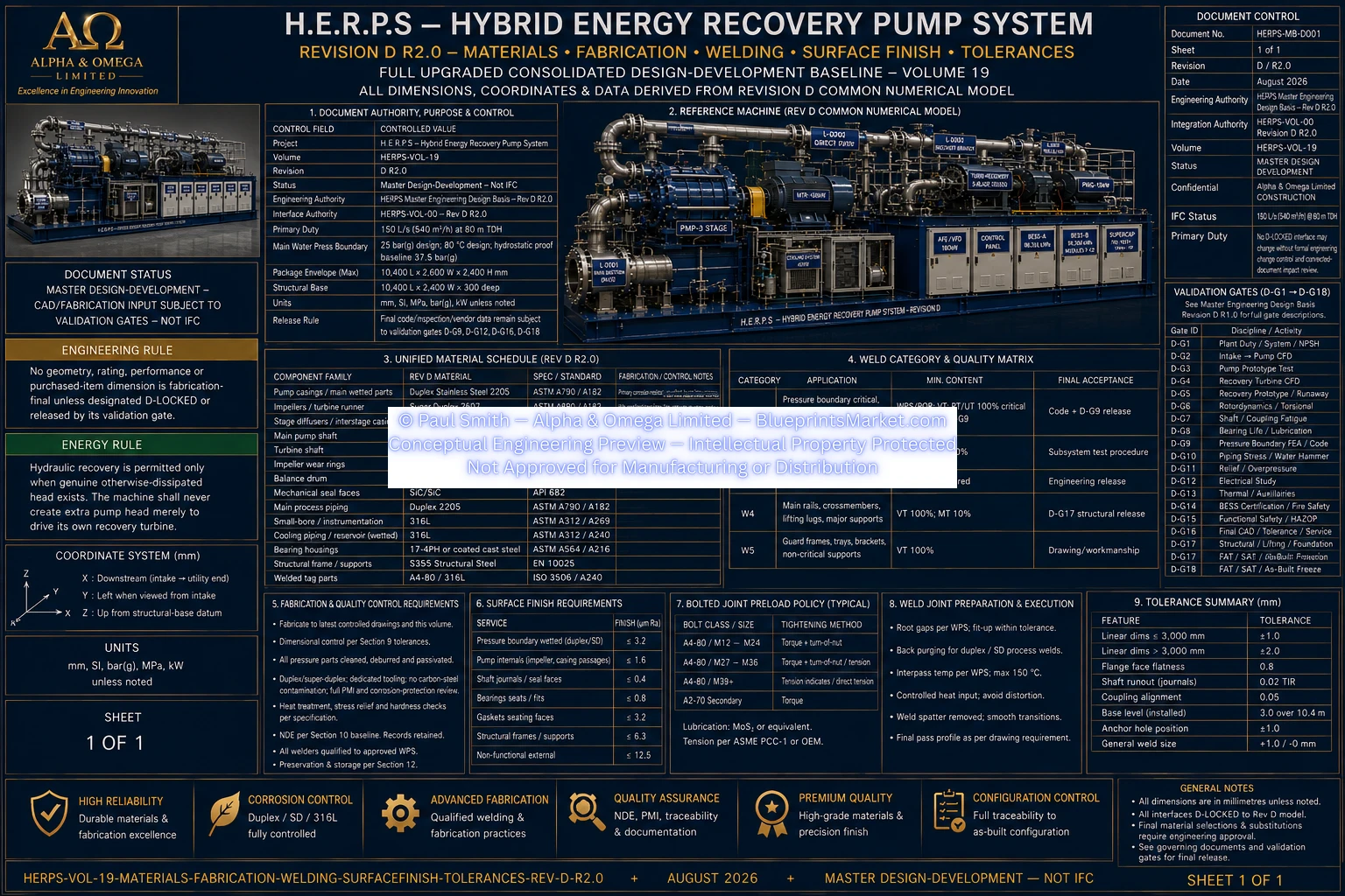
© Paul Smith — Alpha & Omega Limited — PlatformClouds.com — Conceptual Engineering Preview — Not Approved for Manufacturing
HERPS-VOL-19-MATERIALS-FABRICATION-WELDING-SURFACE-FINISH-TOLERANCES-REV-D-R2.0.webp
