© Paul Smith — Alpha & Omega Limited — PlatformClouds.com — Conceptual Engineering Preview — Not Approved for Manufacturing
HERPS-VOL-08-MAIN-HYDRAULIC-PIPING-DISCHARGE-HEADER-VALVES-AND-FLOW-CONTROL-REV-D-R2.0.webp

H.E.R.P.S — HYBRID ENERGY RECOVERY PUMP SYSTEM
Revision D R2.0 — Consolidated Design-Development
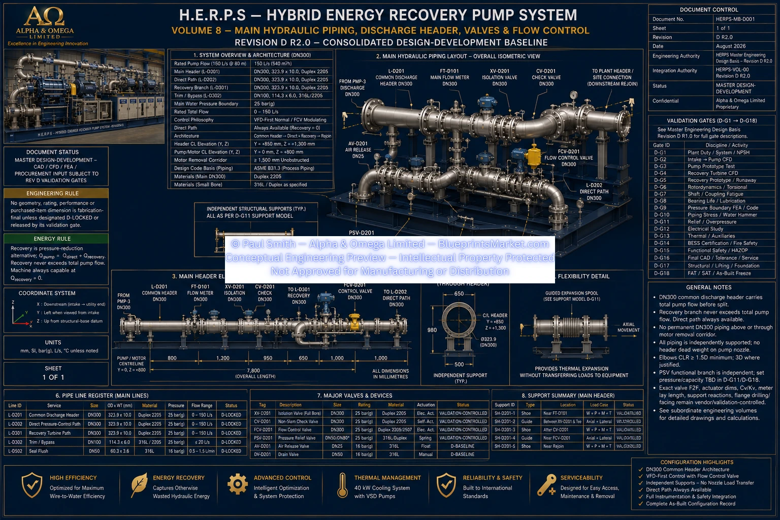
H.E.R.P.S Revision D R2.0 engineering documentation for the main hydraulic discharge and flow-control subsystem, including the DN300 common pump discharge header, DN300 direct pressure-control path, DN300 energy-recovery split and rejoin interface, main flow measurement, discharge isolation, non-slam check protection, modulating flow control, independent mechanical pressure relief, air release, drainage and associated hydraulic instrumentation.
The Revision D hydraulic architecture uses a DN300 common pump discharge header carrying total pump discharge before the system divides into the direct pressure-control path and the hydraulic energy-recovery path.
The direct path remains a required process-flow route. The H.E.R.P.S package is designed to remain capable of safe pumping with the hydraulic energy-recovery turbine unavailable, isolated or disabled.
At the rated operating point, the common discharge header carries 150 L/s, equivalent to 540 m³/h. The Revision D hydraulic mass-balance rule requires total pump flow to equal direct-path flow plus recovery-path flow.
DN300 discharge isolation valve with Duplex 2205 baseline construction, electric actuation and manual override. The Revision D normal position is open, while the final safety fail-state remains subject to the applicable OEM and functional-safety validation.
DN300 self-actuated non-slam check-valve function used to prevent reverse flow. Final closure dynamics and hydraulic loss data are incorporated into the required transient and water-hammer validation.
DN300 direct-path modulating valve used for pressure and flow trimming, hydraulic stability and direct-path takeover during recovery transfer or recovery-system trip. The Revision D baseline is fail-open, subject to final transient and functional-safety validation.
Independent mechanical pressure-relief function retained separately from PLC software. Final relief scenario, set pressure, certified capacity, selected valve orifice and discharge arrangement remain controlled by the dedicated relief-sizing validation.
DN300 full-bore magnetic or ultrasonic main flow measurement with a Revision D measurement range of 0–200 L/s and a target accuracy of no more than 0.5 percent.
Common-discharge pressure measurement with a 0–25 bar(g) range and target accuracy of no more than 0.25 percent full scale.
Pump differential-pressure measurement across two isolated pressure points with a Revision D measurement range of 0–16 bar.
DN25 316L automatic high-point air-release function with root isolation. Final quantity and placement depend on the coordinated trapped-gas geometry.
DN50 316L manual low-point drainage connection with lockable isolation and routing to the defined safe-drain system.
The main pump variable-frequency drive is the primary normal process-control mechanism. In automatic flow mode, pump speed controls the FT-D101 flow measurement. In automatic pressure mode, pump speed controls the required plant pressure target.
FCV-D201 is therefore not intended to waste pump head through routine throttling. Its Revision D role is pressure and flow trimming, hydraulic-stability protection and assumption of direct-path duty during transfer away from the recovery branch.
Hydraulic energy recovery is admitted only when genuine otherwise-wasted pressure head exists and only while required downstream process flow, pressure, pump stability and hydraulic limits remain satisfied.
When recoverable hydraulic head is unavailable, the DN300 direct path carries the required process flow and the recovery path remains closed or at its validated minimum-safe condition.
During partial recovery, the direct path carries the balance of process flow while the recovery branch carries only the validated recoverable portion.
During a recovery-turbine fault or trip, the system transfers safely back to the direct path. The direct-path flow-control function assumes the required hydraulic duty while recovery admission closes or moves to its validated safe condition.
HERPS-VOL-08-MAIN-HYDRAULIC-PIPING-DISCHARGE-HEADER-VALVES-AND-FLOW-CONTROL-REV-D-R2.0.webp
The Revision D discharge architecture routes the large-bore hydraulic header toward the positive-Y side of the package. The nominal main discharge-header centreline is Y=+850 mm and Z=+1300 mm within the coordinated hydraulic discharge/header bay.
This side-routed arrangement preserves the pump and motor service axis and prevents permanent DN300 piping from obstructing the required motor-removal corridor.
Valve dynamics are integrated with the Revision D transient, water-hammer and functional-safety process. Actual check-valve closure behaviour, FCV-D201 stroking behaviour, recovery-path admission and closure, direct-path response, pump coastdown and credible loss-of-power conditions are required inputs to the final transient model.
Independent mechanical pressure relief remains available separately from normal PLC control. Final valve fail states, stroke times, relief settings and protective actions are frozen only after the applicable transient, relief, HAZOP, functional-safety and OEM validation gates have been completed.
This page represents the H.E.R.P.S Revision D R2.0 consolidated design-development hydraulic discharge and flow-control baseline. Exact purchased-valve face-to-face dimensions, flange drilling and facing, actuator envelopes, Cv/Kv values, final relief-valve set pressure and capacity, final support coordinates and reactions, water-hammer results, pump-nozzle allowable loads and site tie-in geometry remain controlled by their applicable OEM, engineering-analysis, validation and site-release processes.
Master Design-Development — Not IFC — Not Shop Release — Not Approved for Manufacturing.