© Paul Smith — Alpha & Omega Limited — PlatformClouds.com —
Conceptual Engineering Preview — Not Approved for Manufacturing
HERPS-VOL-09-HYDRAULIC-ENERGY-RECOVERY-TURBINE-ASSEMBLY-REV-D-R2.0.webp

H.E.R.P.S — HYBRID ENERGY RECOVERY PUMP SYSTEM
HERPS-VOL-09 — Revision D R2.0
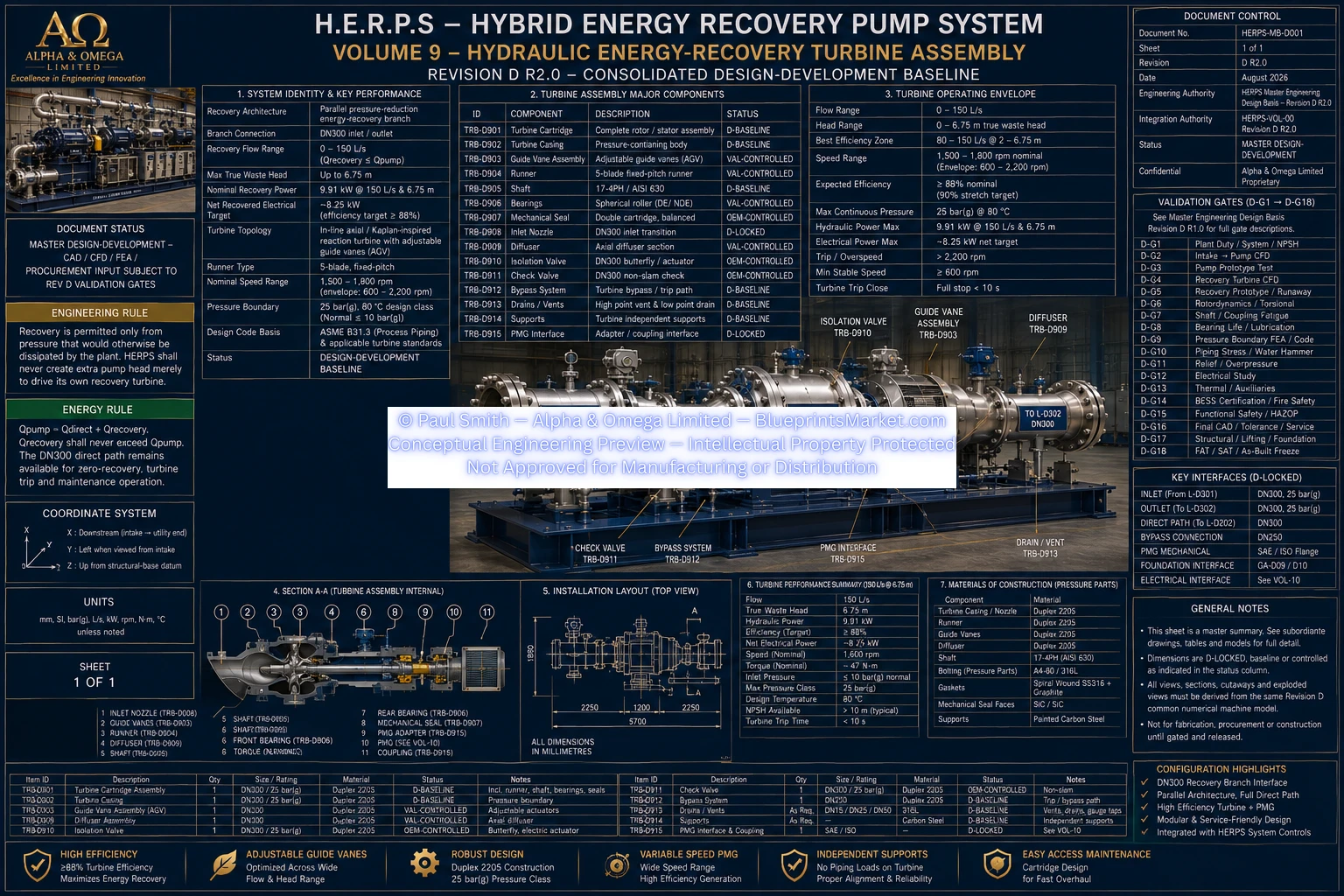
The H.E.R.P.S Hydraulic Energy-Recovery Turbine Assembly is the pressure-energy recovery subsystem of the Hybrid Energy Recovery Pump System. Revision D R2.0 establishes a DN300 parallel pressure-reduction recovery branch incorporating an in-line axial/Kaplan-inspired reaction turbine, adjustable guide vanes, variable-speed permanent-magnet generator interface, pressure housing, diffuser, instrumentation, isolation, check and direct-path fallback functions.
The Revision D turbine architecture operates as a parallel pressure-reduction energy-recovery branch. The full-capacity direct hydraulic path remains available whenever energy recovery is unavailable, unnecessary, outside the validated operating envelope, or isolated for maintenance.
Parallel pressure-reduction energy-recovery branch with full direct process path continuously available.
DN300 turbine inlet and outlet interface.
0–150 L/s, with recovery flow never permitted to exceed measured pump flow.
Up to 6.75 m of genuine otherwise-wasted plant head, dependent on actual site and process conditions.
9.91 kW hydraulic power at 150 L/s and 6.75 m recoverable head.
Approximately 8.25 kW at the stated genuine waste-head condition, subject to validation and selected generator equipment.
The primary pump exists to satisfy the required plant hydraulic duty. Energy recovery must never compromise required downstream pressure, process flow or pump stability.
The recovery turbine is permitted to extract energy only from pressure that would otherwise be dissipated by the plant. H.E.R.P.S does not intentionally increase the pump pressure setpoint merely to create additional turbine power.
The governing hydraulic relationship is:
Qpump = Qdirect + Qrecovery
Recovery flow must never exceed the measured pump flow.
In-line axial/Kaplan-inspired reaction turbine with a fixed-pitch runner, adjustable guide vanes and variable-speed permanent-magnet generator.
Five-blade nominal Revision D development configuration with an approximately 250 mm runner outside diameter.
Approximately 95 mm nominal development baseline.
At least 253 mm nominal for the current 250 mm runner development configuration, maintaining the required radial clearance.
Ten adjustable guide vanes with a 0–25° command range.
Approximately 850–950 mm development envelope, subject to package, OEM and coordinated CAD control.
Super Duplex 2507.
Duplex 2205.
25 bar(g), 80 °C design class with a normal process pressure ceiling of 10 bar(g).
DN300 return diffuser, with an included expansion angle limited to 10° or less where hydraulic expansion is required.
Final pressure-housing wall thickness, reinforcement, flange and joint loads, bolting and hydrotest requirements remain controlled by the applicable Revision D pressure-boundary validation process.
1,500–1,800 rpm.
600–2,200 rpm.
≥88% nominal development target with a 90% stretch objective.
≤2,500 rpm until prototype/runaway validation releases the final hardware trip setting.
Mechanical energy recovered by the hydraulic turbine is coupled to the H.E.R.P.S electrical recovery architecture through a variable-speed permanent-magnet generator and active rectifier.
15 kW permanent-magnet generator.
18 kW where accommodated within the same compliant equipment envelope and selected OEM frame.
≥96% nominal, OEM controlled.
20 kW minimum with a nominal efficiency target of ≥98.5%.
750 VDC nominal common link.
The Revision D hydraulic arrangement retains separate direct and recovery functions so that process duty remains the governing requirement under every operating condition.
DN300 Duplex 2205, 25 bar design class, carrying 0–150 L/s through the recovery turbine path.
DN100 316L/2205, 25 bar, with flow up to 20 L/s for controlled turbine-admission functions.
DN300 common high-pressure source carrying the rated 150 L/s system flow.
DN300 full-capacity process path providing the preferred low-loss route and safe fallback whenever recovery is unavailable.
Recovery pressure measurement before and after the turbine, 0–25 bar(g).
Recovery-flow measurement, 0–180 L/s, with ≤0.5% target.
Turbine speed measurement, 0–3,000 rpm, including independent trip input.
Turbine bearing and structural vibration monitoring, temperature monitoring and stored baseline signatures.
Recovered electrical power, DC voltage/current and generator/rectifier operating status.
Recovery efficiency, recoverable-head margin, valve loss, net recovered power and whole-machine energy performance.
The nominal Revision D recovery turbine / PMG axis is positioned at Y=+950 mm and Z=+850 mm within the coordinated H.E.R.P.S package. Hydraulic and service access is located toward the +Y side.
X=2,500–5,300 mm;
Y=+700 to +1,250 mm;
Z=450–1,450 mm.
Minimum 1,200 mm withdrawal clearance toward +Y.
Minimum 800 mm local pull/lift clearance or greater where required by the selected OEM.
Turbine, valves and piping are independently supported so turbine and pump nozzles do not carry unrelated pipe or valve dead load.
Revision D R2.0 defines the coordinated design-development baseline, but does not fabricate or invent engineering values that remain subject to CFD, prototype testing, rotordynamics, fatigue analysis, bearing analysis, pressure-code verification, transient analysis, HAZOP, OEM data or final coordinated CAD.
Final blade surfaces, guide-vane hydraulic geometry, shaft and bearing dimensions, runaway speed, pressure-housing wall thickness, purchased valve dimensions, actuator envelopes and final recovery-branch fitting coordinates remain controlled by their applicable Revision D validation gates.
HERPS-VOL-09-HYDRAULIC-ENERGY-RECOVERY-TURBINE-ASSEMBLY-REV-D-R2.0.webp
H.E.R.P.S Revision D R2.0 is a consolidated engineering design-development platform. Values identified as validation-controlled, OEM-controlled or site-controlled must be finalized through their governing engineering validation, equipment-selection and site-integration processes before construction or manufacture.