© Paul Smith — Alpha & Omega Limited — PlatformClouds.com —
Conceptual Engineering Preview — Not Approved for Manufacturing
HERPS-VOL-11-THERMAL-MANAGEMENT-AND-COOLING-SYSTEM-REV-D-R2.0.webp

H.E.R.P.S — HYBRID ENERGY RECOVERY PUMP SYSTEM
HERPS-VOL-11 — Revision D R2.0
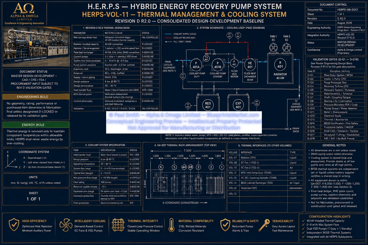
The H.E.R.P.S Revision D thermal-management system provides the closed-loop cooling, heat transport, heat rejection, thermal control and monitoring architecture required by the package's liquid-cooled equipment.
The system is centered on the GA-D07 thermal rack and combines a demand-controlled DN40 316L cooling loop with a 40 kW radiator, two EC variable-speed fans, 40 kW plate heat exchanger, duty/standby VSD circulation pumps, expansion control, reservoir, filtration and thermal instrumentation.
40 kW radiator nameplate basis at corrected worst-case ambient and fouling condition.
0–6 m³/h maximum total demand-controlled flow.
6 bar.
DN40 316L stainless steel supply and return.
Demand-modulated pump and EC-fan operation according to actual thermal requirements.
Two independent cabinet thermal systems unless the selected battery supplier certifies a shared liquid circuit.
The Revision D thermal-management equipment is consolidated within the GA-D07 thermal-rack zone.
| Axis | Revision D GA-D07 Zone |
|---|---|
| X | 6,000–7,500 mm |
| Y | +250 to +1,200 mm |
| Z | 300–1,900 mm |
The radiator and fans occupy the upper portion of the thermal rack, positioned above the plate heat exchanger, circulation pumps, reservoir and associated lower-level thermal equipment.
A minimum 600 mm free radiator-face clearance is retained to support airflow and prevent discharge-air recirculation.
| Parameter | Revision D R2.0 Baseline |
|---|---|
| Installed Heat Rejection | 40 kW |
| Envelope | 1,400 W × 900 D × 1,100 H mm |
| Fans | 2 × EC variable-speed fans |
| Location | Upper GA-D07 thermal rack |
| Selection Basis | Worst project ambient with fouling and altitude correction |
Final fin density, tube construction, coolant-side pressure drop, fan static pressure, sound power, motor power, environmental rating and exact mounting remain vendor-controlled.
Two EC fans are integrated with the radiator assembly and provide modulated airflow according to actual heat-rejection demand.
Fan operation is coordinated with coolant temperature and the three-way temperature-control valve rather than operating continuously at maximum speed.
Fan status and fault feedback are incorporated where supported by the selected radiator/fan package.
| Parameter | Revision D R2.0 Baseline |
|---|---|
| Type | Plate heat exchanger |
| Material | 316L stainless steel |
| Duty | 40 kW |
| Effective Area | 3–5 m² development baseline |
| Connections | DN40 |
| Cooling-Loop Interface | 6 bar |
| Process-Side Pressure Where Applicable | 25 bar |
Final plate count, channel pattern, approach temperature, pressure drop, fouling factor and construction are subject to the final thermal model and selected vendor.
2 pumps.
1 duty + 1 standby.
Each pump up to 6 m³/h.
Approximately 2.5 bar.
Variable-speed, demand-modulated operation.
Automatic takeover following duty-pump failure or failure to establish adequate flow where the cause/effect permits.
| Volume | 50 L |
|---|---|
| Type | Diaphragm expansion tank |
| Pressure Rating | 6 bar |
| Function | Closed-loop expansion and pressure stabilization |
| Volume | 80 L |
|---|---|
| Material | 316L stainless steel |
| Internal Construction | Baffled |
| Drain | Required |
| Level Measurement | LT-401 continuous 0–100% |
| Function | Reservoir, deaeration and service volume |
The main cooling loop incorporates a 100 micron filtration baseline to protect the motor, VFD/electronics cooling passages and other thermal equipment.
Differential-pressure indication is required so restriction and filter condition can be monitored.
DN40.
Modulating thermal control.
Bypass, mixing or diverting action according to the final cooling P&ID and control strategy.
Exact Cv/Kv, actuator configuration, fail position and control characteristic remain validation/vendor controlled.
| Line | Size / Material | Pressure | Duty |
|---|---|---|---|
| L-401S — Cooling Supply | DN40; OD 48.3 × 3.7; 316L | 6 bar | 0–6 m³/h maximum demand-controlled flow |
| L-401R — Cooling Return | DN40; OD 48.3 × 3.7; 316L | 6 bar | 0–6 m³/h maximum demand-controlled flow |
| L-402 — Fill / Vent / Expansion | DN20; OD 26.9 × 2.6; 316L | 6 bar | Intermittent service |
High-point venting and low-point drainage are provided where the physical arrangement can trap air or liquid.
The primary motor uses a closed-loop water-jacket cooling interface. Volume 11 supplies coolant within the main cooling-loop envelope, while final branch flow, pressure and permitted temperature limits remain controlled by the selected motor OEM.
Liquid-cooled VFD/AFE and converter branches are integrated into the DN40 loop where required by selected equipment. Air-cooled equipment remains outside the liquid-loop heat allocation and must be addressed through the applicable ventilation architecture.
The 15 kW recovery PMG remains air cooled with a 1 kW thermal-loss allowance and is not a locked main-loop liquid load.
Revision D maintains two independent BESS cabinet thermal systems. They are not connected to the main liquid loop unless the selected battery supplier explicitly certifies a shared cooling arrangement.
Final internal battery cooling hardware, refrigerant system, condensation control, module thermal interfaces, temperature setpoints and fire-response interaction remain battery-supplier controlled.
| Instrument | Quantity / Range | Function |
|---|---|---|
| T09 / FT-401 | 1 — 0–10 m³/h | Main cooling-loop flow measurement |
| T10 Pt100 Temperature Sensors | 6 | Motor inlet/outlet, VFD loop, radiator inlet/outlet and ambient |
| T11 Pressure Sensors | 2 — 0–6 bar class | Supply/return pressure and loop performance context |
| LT-401 | 0–100% | Continuous coolant-reservoir level |
Revision D specifically replaces unnecessary fixed-speed cooling operation with demand-controlled thermal management.
Duty-pump speed and EC-fan command follow actual thermal demand, minimum stable flow, equipment cooling requirements and validated control margins.
At low heat load or cold ambient conditions, the three-way valve may bypass or mix flow to avoid overcooling. As coolant temperature rises, radiator exposure and EC-fan demand increase.
Automatic standby takeover plus alarm.
Low-flow protective sequence for heat-producing equipment.
Alarm and reassessment/derating of remaining cooling capacity.
Differential-pressure indication and maintenance response.
Level, pressure and flow indications support controlled shutdown.
BMS/supplier thermal isolation and applicable fire-response strategy.
Volume 11 establishes the complete source-supported thermal architecture but deliberately does not fabricate final values where selected equipment, site conditions or validation calculations are required.
Final coolant chemistry, ambient and altitude design point, radiator/fan performance curves, PHE approach and plate count, loop pressure-drop and pump-NPSH calculation, purchased pump and valve dimensions, branch-flow balancing, converter heat-loss data, BESS supplier thermal construction and final alarm/trip limits remain controlled by OEM, site and Revision D validation processes.
Revision D R2.0 Consolidated Design-Development — Not IFC — Not Fabrication-Final.
HERPS-VOL-11-THERMAL-MANAGEMENT-AND-COOLING-SYSTEM-REV-D-R2.0.webp