H.E.R.P.S — Engineering Validation, Analysis & Design Optimization
Revision D R2.0 — Engineering Analysis • Validation Gates • Design Freeze • FAT/SAT Acceptance
Hybrid Energy Recovery Pump System (H.E.R.P.S)
Revision D Engineering Validation Framework
H.E.R.P.S Revision D R2.0 uses a formal engineering validation and
design-freeze process rather than treating development targets,
simulations or preliminary calculations as final verified results.
Hydraulic, rotating, structural, pressure-boundary, electrical,
thermal, control, energy-storage and site-interface disciplines are
progressively validated through controlled engineering gates before
the corresponding configuration can be frozen for downstream release.
- Engineering-analysis governance
- Hydraulic CFD validation
- Prototype hydraulic testing
- Q-H, efficiency and power verification
- NPSHR verification
- Rotordynamic analysis
- Critical-speed and exclusion-band validation
- Shaft stress and fatigue assessment
- Bearing-life and lubrication validation
- Pressure-boundary engineering
- Piping and transient analysis
- Electrical-system studies
- Thermal-performance validation
- BESS and supercapacitor verification
- Functional-safety validation
- Manufacturing and tolerance control
- FAT / SAT / commissioning evidence
- Formal design freeze
Revision D Controlled System Baseline
| System Parameter |
Revision D R2.0 Baseline |
| Rated Pump Duty |
150 L/s at 80 m TDH |
| Main Pump |
Horizontal three-stage variable-speed centrifugal pump |
| Main Pressure Boundary |
25 bar(g), 80 °C design baseline |
| Hydrotest Development Baseline |
37.5 bar(g), subject to final code validation |
| Main Hydraulic Interfaces |
DN350 suction / DN300 discharge / DN300 recovery architecture |
| Main Drive |
160 kW liquid-cooled IE5-class SynRM development baseline |
| Drive Power Electronics |
400 VAC regenerative AFE/VFD, ≥180 kW continuous class |
| Common DC Link |
750 VDC nominal; 650–800 V controlled |
| BESS |
192S / 160 Ah / 614.4 VDC nominal / 98.304 kWh |
| Supercapacitor |
750 V / 16 F nominal; ≥250 kW short-duration converter |
| Maximum Package Envelope |
10,400 × 2,600 × 2,400 mm |
Validation Governance
Each Revision D validation gate is controlled through an identified
engineering discipline, released input revision set, approved method,
documented results, acceptance criteria, non-conformance status and
formal sign-off.
- Responsible engineering discipline identified
- Independent checker or reviewer where required
- Controlled input drawings and model revisions
- Defined analysis or test procedure
- Recorded calculated or measured results
- Defined acceptance criterion
- NCR and action status recorded
- Affected drawings and documents updated
- Gate decision recorded as PASS / CONDITIONAL / FAIL
- Freeze level formally released
- Approval and date recorded
Objective Evidence — Not Target Values
Revision D does not allow a validation gate to be declared passed merely
because a design target or simulation value exists. A gate is closed only
when traceable objective evidence demonstrates that the approved release
criterion has been satisfied.
Where validation changes an assumed baseline, the revised result is
propagated through the controlled interface architecture, drawings,
BOM, controls, test procedures and downstream validation inputs before
further release.
- Targets are not automatically acceptance results
- Simulation is not automatically certification
- Calculated values remain identified as calculated where applicable
- Measured values require controlled test evidence
- Conditional or failed gates remain formally open
- Temporary deviations require controlled disposition
Hydraulic CFD & Pump Performance Validation
The hydraulic-core design is validated through numerical analysis and
prototype testing before final hydraulic surfaces and performance
characteristics are frozen.
- Three-stage hydraulic-core CFD
- Impeller and diffuser flow-field evaluation
- Internal recirculation assessment
- Hydraulic radial-load prediction
- Hydraulic axial-thrust prediction
- Cavitation-risk assessment
- Predicted Q-H performance
- Predicted hydraulic efficiency
- Predicted shaft-power demand
- Prototype confirmation of CFD predictions
Prototype Hydraulic Testing
Prototype hydraulic testing converts the validated development geometry
into measured performance evidence and establishes the released operating
map.
- Measured Q-H curve
- Measured pump efficiency
- Measured shaft/electrical power relationship
- NPSHR testing
- Stable operating-range confirmation
- Hydraulic thrust confirmation
- Operating-envelope definition
- Performance repeatability
Rotor, Shaft & Rotordynamic Validation
The rotating assembly is validated as a complete dynamic system rather
than by checking shaft geometry alone.
- Rotor-mass and inertia model
- Bearing stiffness and damping model
- Coupling influence
- Critical-speed analysis
- Campbell-diagram evaluation
- Mode-shape assessment
- Unbalance-response analysis
- Transient-speed behavior
- Operating exclusion-band definition where required
- Validation against FAT speed-sweep evidence
Shaft Stress, Fatigue & Mechanical Integrity
The Revision D shaft and rotating assembly are checked against combined
torsional, bending, axial and dynamic loading over the defined operating
envelope.
- Static shaft-stress assessment
- Combined bending and torsion
- Axial-load effects
- Stress-concentration assessment
- Fatigue evaluation
- Coupling-interface loading
- Journal and shoulder integrity
- Runout and straightness control
- Balance-quality verification
Bearing-Life & Support-System Validation
Bearing validation combines hydraulic reaction loads, rotor dynamics,
lubrication condition, temperature, electrical exposure and selected
supplier data.
- DE locating-bearing load assessment
- NDE floating-bearing load assessment
- OEM bearing-life calculation
- Lubricant viscosity validation
- Temperature stabilization testing
- Vibration signature acceptance
- Axial thermal-growth verification
- Electrical bearing-current assessment
Pressure-Boundary & Hydraulic Integrity Validation
Pump casing, pressure-containing joints, main hydraulic piping and
recovery equipment are validated against the Revision D pressure class
and the selected project code basis.
- Pressure-boundary stress verification
- Flange and joint validation
- Pressure-containing fastener verification
- Hydrostatic test definition
- Leak testing
- Relief-system engineering
- Hydraulic transient assessment
- Water-hammer analysis
- Piping stress and support verification
Energy Balance & Recovery Physics Validation
Revision D preserves fundamental hydraulic and thermodynamic conservation
throughout the recovery architecture.
Qpump = Qdirect + Qrecovery
The recovery turbine is permitted to use only genuinely available
otherwise-wasted pressure reduction. Additional pump head is not created
merely to increase recovery output.
- Measured pump flow remains the governing flow source
- Recovery flow cannot exceed actual pump flow
- Recovery head must physically exist at the recovery point
- Recovered electrical output is verified from measured hydraulic conditions
- No self-powering or perpetual-energy assumption is used
Electrical-System Validation
- 400 VAC plant-interface verification
- AFE/VFD rated-operation verification
- Motor protection verification
- Electrical fault-level studies
- Protective-device coordination
- Common DC-link behavior
- DC overvoltage protection
- Bidirectional DC/DC converter testing
- Recovery rectifier validation
- Protective bonding and electrical safety verification
BESS, DC/DC & Supercapacitor Validation
- BESS architecture verification
- BMS protective-function verification
- Precharge sequence testing
- Insulation-monitoring verification
- DC/DC power-transfer testing
- Electrical isolation testing
- Supercapacitor charge/discharge verification
- Transient-energy support testing
- DC-link OVP verification
- Controlled discharge verification
Thermal-System Validation
Thermal validation confirms that the machine's motor, drive electronics,
recovery electronics and other heat-producing equipment remain within
released operating limits throughout the intended duty envelope.
- Coolant-flow verification
- Temperature stability
- Demand-controlled cooling validation
- Thermal endurance testing
- Fault and degraded-mode evaluation
- Temperature sensor validation
Materials, Fabrication & Manufacturing Validation
Revision D extends validation into manufacturing so material identity,
fabrication quality, welding, machining, surface finish and dimensional
conformity remain traceable to the released design.
- Material certification
- Heat and batch traceability
- Welding procedure qualification
- Welder qualification
- Weld inspection and NDE
- Machining tolerances
- Geometric tolerances
- Surface-finish requirements
- Passivation and coating records
- Dimensional inspection records
- Manufacturing NCR control
Interface Consistency Audit
Before release, the frozen configuration is audited so that hydraulic,
rotating, electrical, structural, controls and site interfaces remain
mutually consistent.
- 150 L/s / 80 m TDH system identity preserved
- Three-stage pump identity preserved
- 160 kW drive baseline reconciled
- Hydraulic flow conservation maintained
- 25 bar pressure-class basis consistently applied
- Rotor and bearing interfaces reconciled
- 400 VAC / 750 VDC architecture reconciled
- BESS architecture preserved
- Package envelope and maintenance access preserved
- Foundation and lifting data reconciled
- Safety cause/effect reflected consistently across all documents
Design Optimization Under Controlled Constraints
Optimization is performed only inside the validated physical and safety
boundaries of the system. Improvements to hydraulic efficiency, energy
consumption, recovery operation, thermal demand or control response may
not invalidate another released engineering discipline.
- Hydraulic efficiency optimization
- Minimum-specific-energy operation
- Recovery-path optimization
- Drive-speed optimization
- Thermal-demand optimization
- Transient-energy management
- Maintenance-access optimization
- Manufacturing and tolerance optimization
- Whole-machine rather than isolated-component optimization
Formal Design Freeze
Design freeze is progressive. A subsystem is frozen only after its
controlling validation evidence and dependent interfaces are sufficiently
mature for release.
- Establish controlled Revision D design inputs.
- Complete applicable analysis and simulation.
- Complete prototype or component testing where required.
- Resolve non-conformances and validation actions.
- Update affected drawings, models, BOM and controls.
- Complete interface consistency review.
- Sign the applicable validation gate.
- Release the corresponding design-freeze level.
- Verify the frozen configuration through FAT/SAT and as-built records.
FAT, SAT & Performance Acceptance
The final engineering-validation process culminates in objective factory
and site evidence demonstrating that the released configuration performs
as intended.
- Configuration and document audit
- Dimensional survey
- Hydrostatic and leak testing
- Pump Q-H testing
- Pump efficiency and power measurement
- NPSHR verification
- Vibration and speed-sweep testing
- Bearing-temperature verification
- Motor / VFD testing
- Recovery turbine / PMG testing
- BESS / DC-DC testing
- Supercapacitor / DC-link testing
- Thermal-management testing
- Instrumentation loop checks
- Trip and interlock verification
- Integrated endurance testing
- Site hydraulic-profile verification
- Foundation / anchor / alignment verification
- As-built records
- Final signed acceptance
Measured Acceptance — No False Finalization
Final acceptance is based upon traceable test and inspection evidence.
Revision D does not invent successful hydraulic curves, NPSHR results,
vibration readings, bearing temperatures, electrical fault ratings,
BESS certification, foundation adequacy or recovery output.
Those values become accepted only when the applicable engineering gate,
FAT, SAT, commissioning or signed as-built evidence exists.
Revision D Engineering Status
This page presents the public-facing Revision D R2.0 engineering
validation and design-optimization framework. It does not expose or
substitute the purchaser-controlled calculation files, supplier-final
data, detailed manufacturing records, released settings or signed
production as-built dossier.
Revision D remains a controlled master design-development system until
the applicable engineering, validation, procurement, fabrication,
testing and final configuration-freeze processes have been completed.
Explore the Complete H.E.R.P.S Revision D Engineering System
Engineering analysis, validation gates and design freeze connect the
hydraulic, mechanical, electrical, structural, control, fabrication,
commissioning and as-built disciplines across the complete H.E.R.P.S
Revision D engineering package.
View the Complete HERPS System
Contact Blueprints Market for product,
licensing and engineering-package enquiries.
REVISION D — MASTER DESIGN BASIS • MANUFACTURING CONTROL • VALIDATION GATES • FAT/SAT ACCEPTANCE
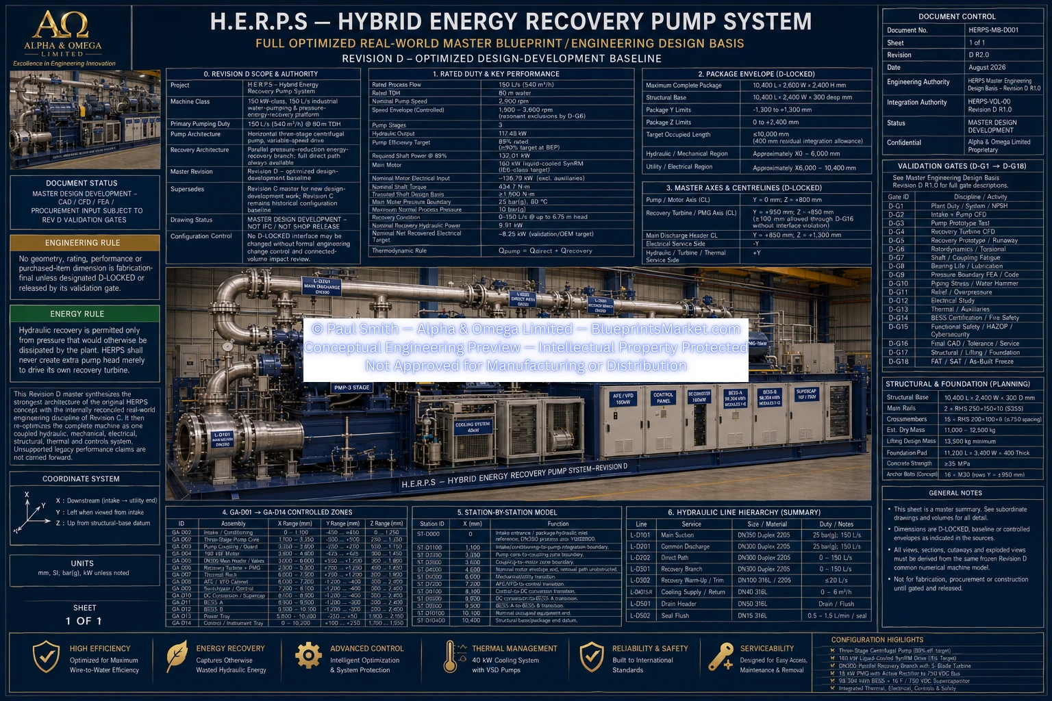
© Paul Smith — Alpha & Omega Limited — PlatformClouds.com — Conceptual Engineering Preview — Not Approved for Manufacturing
HERPS_MASTER_ENGINEERING_DESIGN_BASIS_REV_D_R2.0.webp
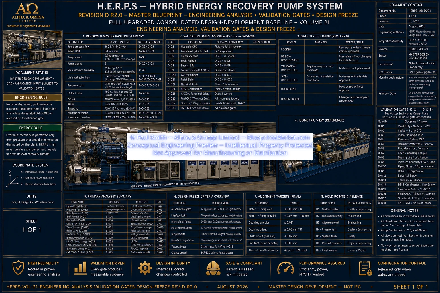
© Paul Smith — Alpha & Omega Limited — PlatformClouds.com — Conceptual Engineering Preview — Not Approved for Manufacturing
HERPS-VOL-21-ENGINEERING-ANALYSIS-VALIDATION-GATES-AND-DESIGN-FREEZE-REV-D-R2.0.webp
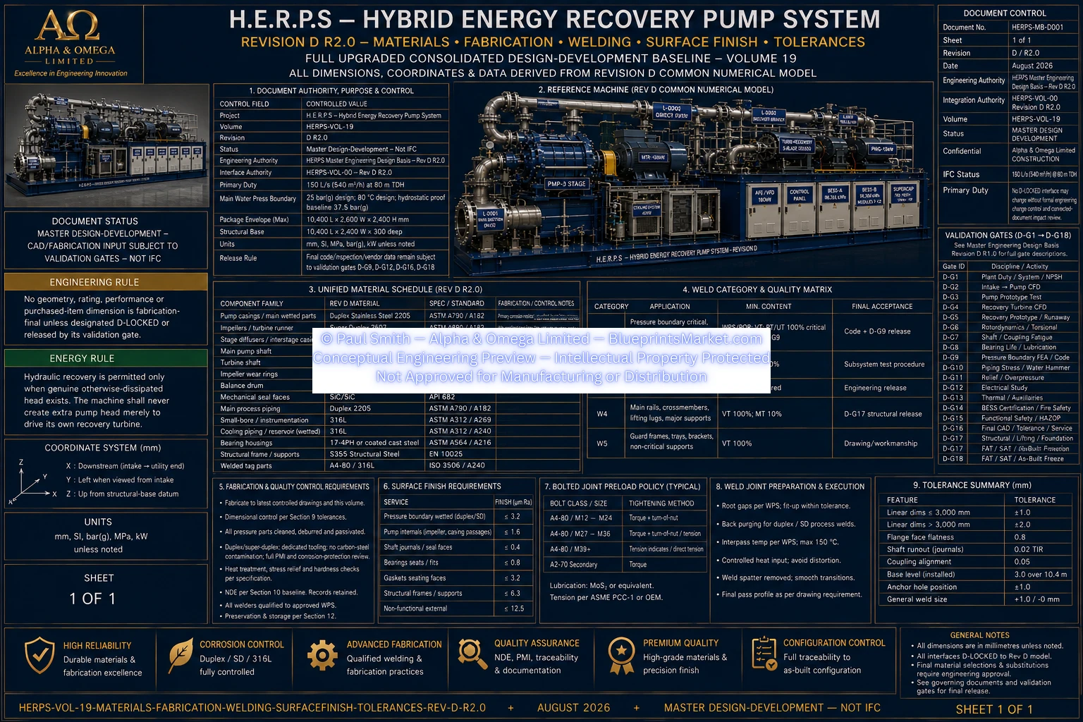
© Paul Smith — Alpha & Omega Limited — PlatformClouds.com — Conceptual Engineering Preview — Not Approved for Manufacturing
HERPS-VOL-19-MATERIALS-FABRICATION-WELDING-SURFACE-FINISH-TOLERANCES-REV-D-R2.0.webp
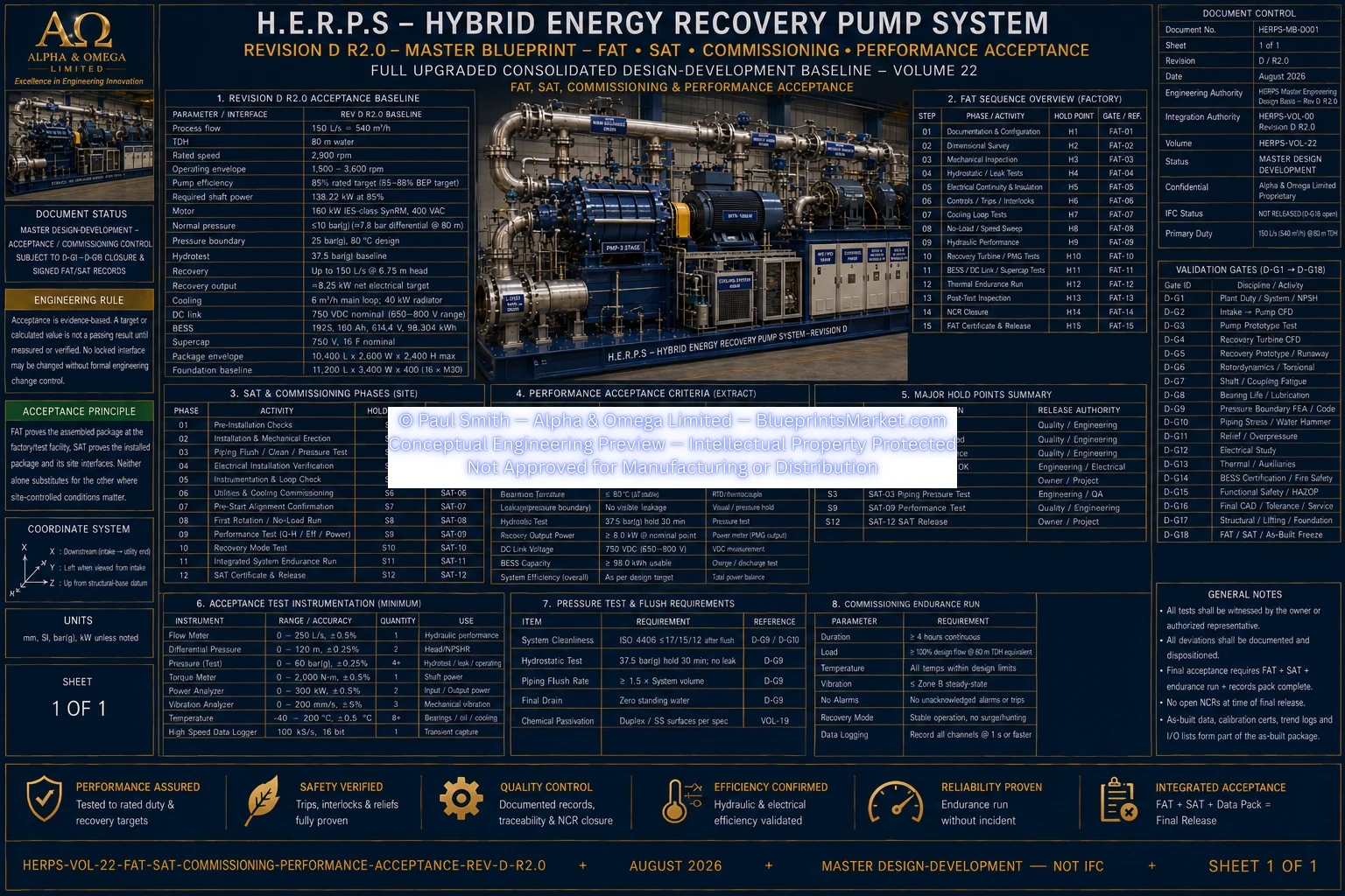
© Paul Smith — Alpha & Omega Limited — PlatformClouds.com — Conceptual Engineering Preview — Not Approved for Manufacturing
HERPS-VOL-22-FAT-SAT-COMMISSIONING-PERFORMANCE-ACCEPTANCE-REV-D-R2.0.webp
