© Paul Smith — Alpha & Omega Limited — PlatformClouds.com — Conceptual Engineering Preview — Not Approved for Manufacturing
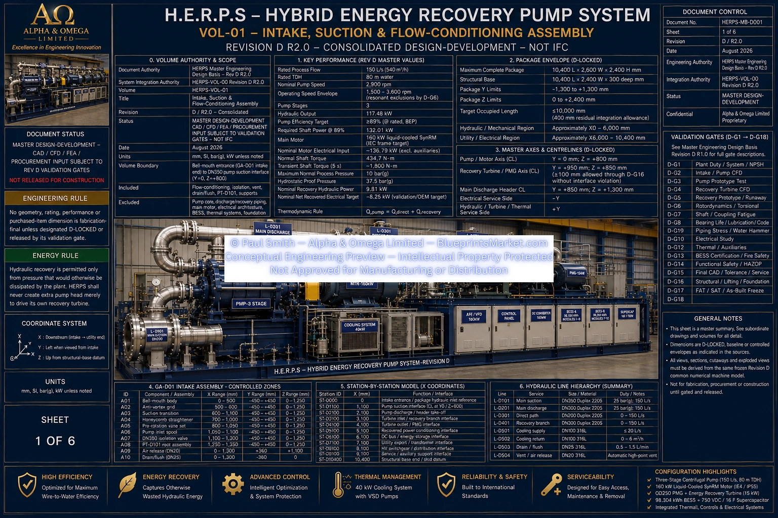
HERPS-VOL-01-INTAKE-SUCTION-FLOW-CONDITIONING-ASSEMBLY-SHEET-1-OF-6-REV-D-R2.0.webp

Revision D R2.0 — Intake / Suction / Flow Conditioning Assembly
Engineering overview of the H.E.R.P.S Revision D intake, suction and flow-conditioning subsystem forming the controlled hydraulic entrance path to the primary pump system.
The H.E.R.P.S intake, suction and flow-conditioning assembly provides the hydraulic entrance path into the pump system and incorporates the components required to condition and control the incoming fluid before it reaches the primary pump inlet.
The assembly is designed around controlled intake geometry, suction piping, flow conditioning, vortex control, instrumentation, isolation, venting, drainage and structural support provisions.
The intake section establishes the initial hydraulic entrance into the H.E.R.P.S system. Its geometry is arranged to provide a controlled transition from the incoming fluid source into the main suction flow path.
The intake arrangement works together with the downstream flow-conditioning components to reduce undesirable inlet disturbances before the fluid reaches the pump suction interface.
The suction flow path connects the intake assembly to the primary pump inlet and establishes the principal hydraulic route through the flow-conditioning subsystem.
The suction assembly incorporates the required transition sections, straight pipe sections, isolation provisions, instrumentation connections and associated fittings required by the Revision D configuration.
Flow-conditioning elements are incorporated into the intake and suction assembly to manage inlet-flow quality before the fluid enters the pump.
These provisions address large-scale vortex formation, residual swirl, non-uniform velocity distribution and other upstream disturbances that can adversely affect pump inlet conditions.
The Revision D intake arrangement incorporates dedicated provisions for controlling undesirable vortex and swirl behaviour within the incoming hydraulic flow.
The purpose of these components is to improve the quality and uniformity of the flow delivered to the downstream suction path while avoiding unnecessary restriction of the primary hydraulic passage.
Instrumentation provisions within the suction system provide the measurement points required to monitor hydraulic conditions associated with the pump inlet.
These measurement provisions support commissioning, operational monitoring, hydraulic validation and assessment of the actual suction conditions experienced by the pump system.
The intake and suction assembly incorporates venting and drainage provisions to support filling, commissioning, controlled removal of trapped gas, draining, flushing and maintenance activities.
These service connections form part of the integrated Revision D hydraulic assembly and are positioned in accordance with their required operational functions.
The intake and suction piping assembly is supported as part of the mechanical installation so that connected piping, valves and associated components do not impose uncontrolled structural loading or alignment disturbance on the pump inlet.
Support and alignment provisions form part of the complete installation arrangement and are coordinated with the H.E.R.P.S skid, pump assembly and connected piping system.
HERPS-VOL-01-INTAKE-SUCTION-FLOW-CONDITIONING-ASSEMBLY-SHEET-1-OF-6-REV-D-R2.0.webp
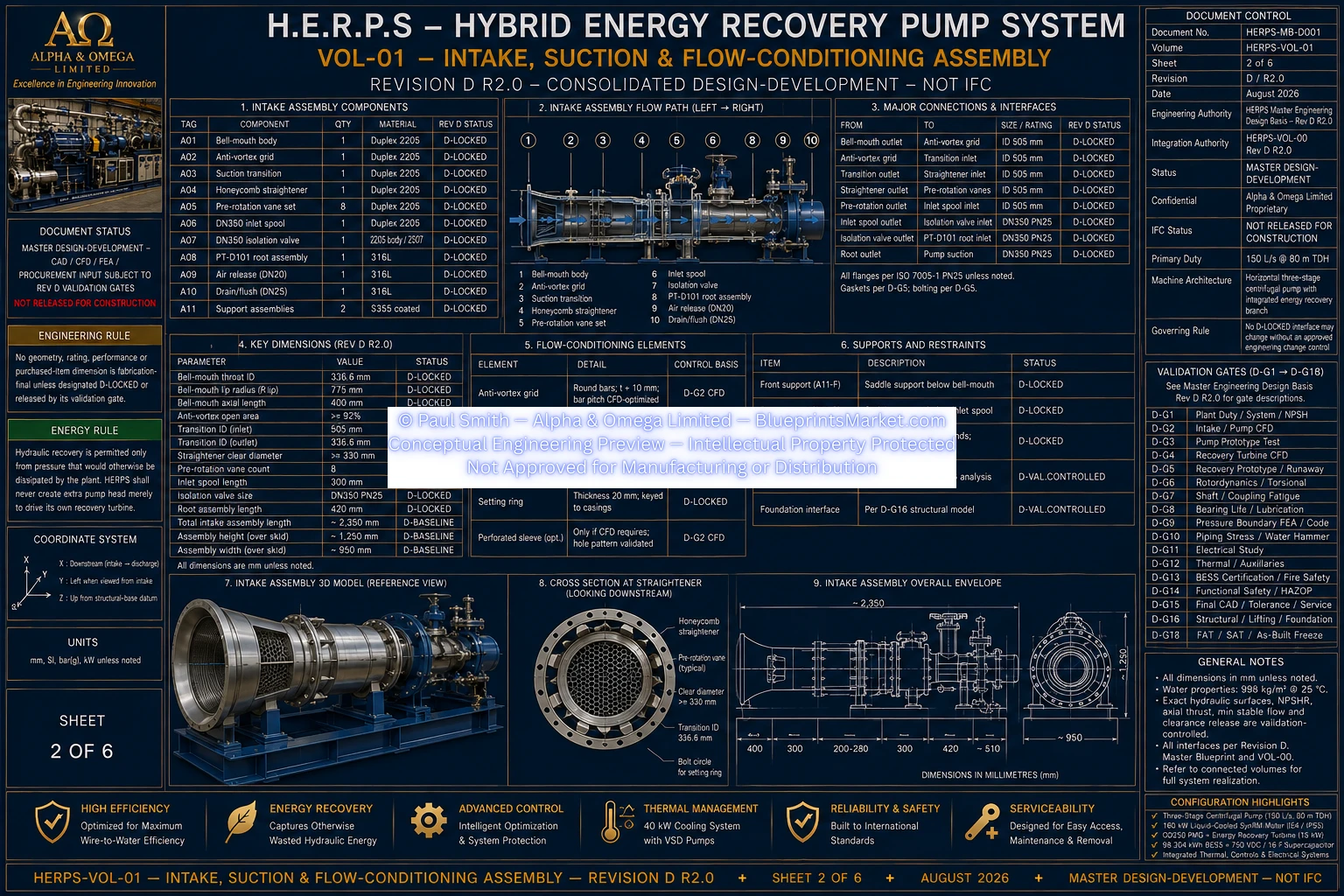
HERPS-VOL-01-INTAKE-SUCTION-FLOW-CONDITIONING-ASSEMBLY-SHEET-2-OF-6-REV-D-R2.0.webp
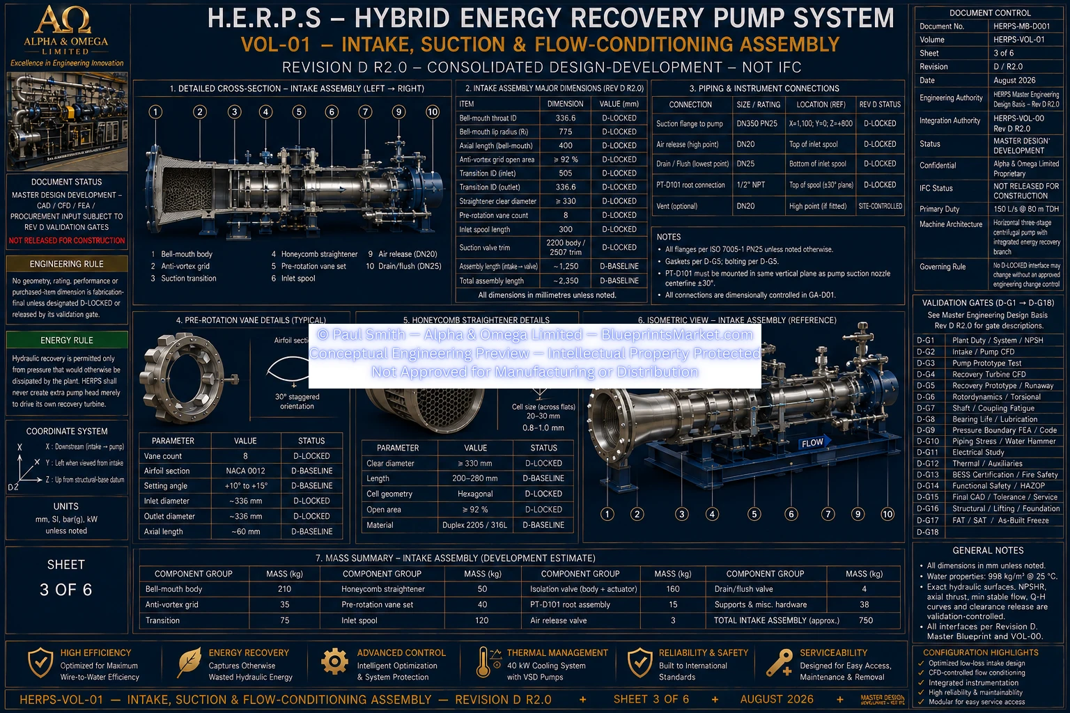
HERPS-VOL-01-INTAKE-SUCTION-FLOW-CONDITIONING-ASSEMBLY-SHEET-3-OF-6-REV-D-R2.0.webp
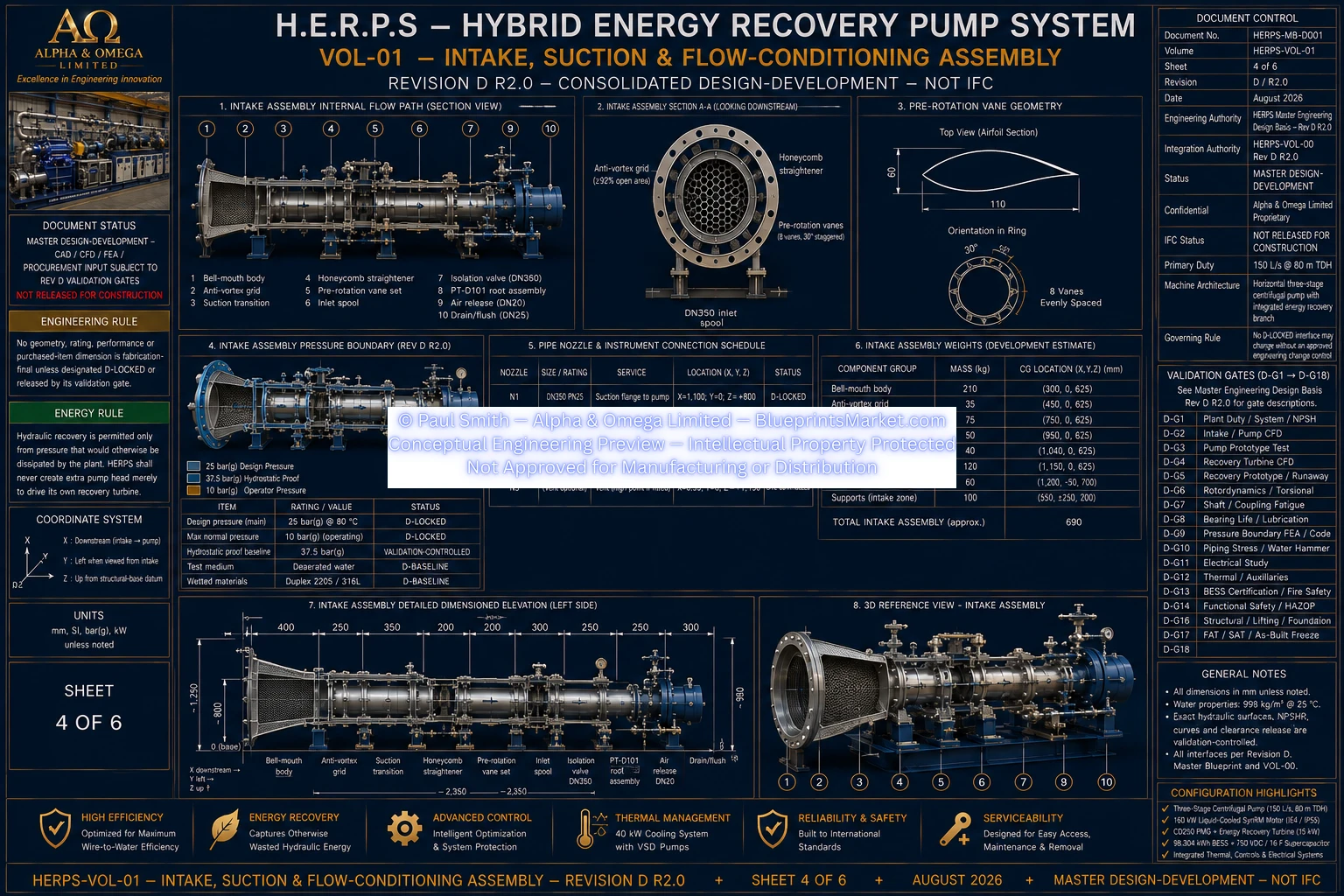
HERPS-VOL-01-INTAKE-SUCTION-FLOW-CONDITIONING-ASSEMBLY-SHEET-4-OF-6-REV-D-R2.0.webp
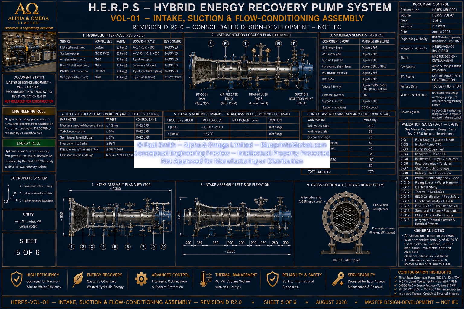
HERPS-VOL-01-INTAKE-SUCTION-FLOW-CONDITIONING-ASSEMBLY-SHEET-5-OF-6-REV-D-R2.0.webp
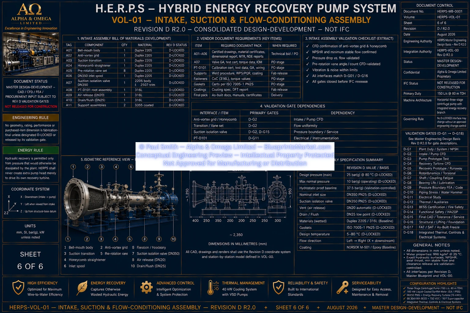
HERPS-VOL-01-INTAKE-SUCTION-FLOW-CONDITIONING-ASSEMBLY-SHEET-6-OF-6-REV-D-R2.0.webp
This page presents the H.E.R.P.S Revision D R2.0 intake, suction and flow-conditioning assembly as part of the current engineering documentation set.
The associated blueprint sheets are presented as conceptual engineering previews and are not approved for manufacturing.