© Paul Smith — Alpha & Omega Limited — PlatformClouds.com —
Conceptual Engineering Preview — Not Approved for Manufacturing
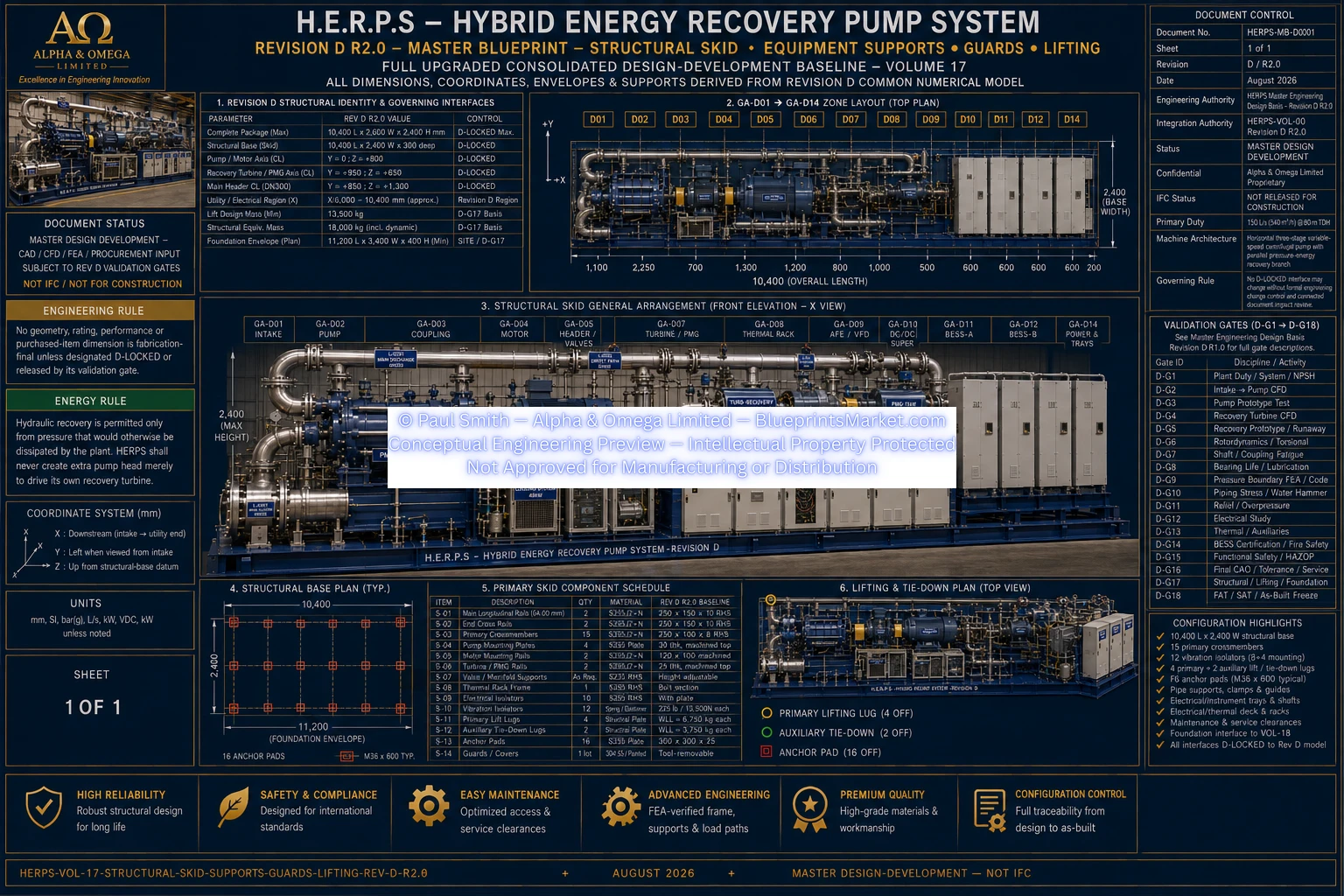
HERPS-VOL-17-STRUCTURAL-SKID-EQUIPMENT-SUPPORTS-GUARDS-AND-LIFTING-REV-D-R2.0.webp

H.E.R.P.S — HYBRID ENERGY RECOVERY PUMP SYSTEM
HERPS-VOL-17 — Revision D R2.0
The H.E.R.P.S Revision D structural package is built around one continuous 10,400 mm S355 structural skid supporting the complete hydraulic, rotating, thermal, electrical, energy-storage and control package.
Volume 17 controls the primary structural rails and crossmembers, pump and motor mounting interfaces, recovery turbine and PMG rails, large-bore piping and valve supports, thermal rack, electrical deck, vibration isolation, guarding, lifting and tie-down provisions, anchor pads, bonding interfaces and structural load paths.
10,400 L × 2,600 W × 2,400 H maximum.
10,400 L × 2,400 W × 300 deep.
Y=0, Z=+800.
Nominal Y=+950, Z=+850.
13,500 kg minimum until actual approved lift-state mass is frozen.
18,000 kg including dynamic and handling allowance.
| Structural Item | Quantity | Revision D R2.0 Baseline |
|---|---|---|
| Main longitudinal rails | 2 | S355 RHS 250×150×10; length 10,400 mm |
| End cross rails | 2 | S355 RHS 250×150×10; width 2,400 mm |
| Primary crossmembers | 15 | S355 RHS 200×100×8; approximately 2,100 mm clear; ≤750 mm nominal spacing |
| Pump mounting plates | 4 | S355 plate 300×220×25; machined top |
| Motor mounting rails | 2 | S355 1,200×180×30; machined top |
| Recovery turbine / PMG rails | 2 | S355 1,800×120×20 baseline |
| Valve / manifold supports | As required | S355 RHS 100×100×6 minimum before final support calculation |
The two 10,400 mm longitudinal rails act as the principal package beams. The two end rails and fifteen primary crossmembers form one continuous full-package structural base.
Rotating equipment, DN350/DN300 piping and valves, the recovery train, thermal hardware and electrical/BESS cabinets transfer dead, operating, transient, service and handling loads through dedicated supports into the primary skid.
Pump and turbine nozzles and instrument connections are not used as structural supports. Large valves, vertical piping runs and other concentrated masses require independent support.
Four 300×220×25 mm S355 machined mounting plates.
Two 1,200×180×30 mm S355 machined rails for the Revision D 160 kW liquid-cooled SynRM baseline.
Finish-machined after skid welding and structural stabilization.
≤0.25 mm before shimming.
≤0.10 mm.
Parallel ≤0.05 mm and angular ≤0.05° with hot-growth correction.
Motor removal requires at least 1,500 mm unobstructed clearance, and permanent DN300 piping must not pass above or through the motor removal axis.
Revision D supersedes the earlier DN250 support concept with a DN300 recovery branch and DN300 axial/Kaplan-inspired recovery cartridge.
2 × S355, 1,800×120×20 mm baseline.
Nominal Y=+950, Z=+850.
X=2,500–5,300; Y=+700..+1,250; Z=450..1,450.
≥1,200 mm toward +Y.
≥800 mm local clearance.
Piping loads are isolated from the turbine cartridge and PMG train.
| Service | Revision D Line | Structural Rule |
|---|---|---|
| Intake | DN350 Duplex 2205 | Independent support; preserve Y0/Z800; no pump-nozzle weight |
| Common discharge | DN300 Duplex 2205 | Independent riser/header/valve supports |
| Direct path | DN300 Duplex 2205 | Support valves/check devices without nozzle loading |
| Recovery branch | DN300 Duplex 2205 | Independent branch support to turbine throat and rejoin |
| Cooling | DN40 316L | Preserve service access and drainability |
| Drain / seal flush | DN50 / DN15 | Support without instrument or root-valve interference |
The Revision D thermal rack occupies GA-D07, approximately X=6,000–7,500, Y=+250..+1,200 and Z=300..1,900.
The baseline rack uses S355 RHS 80×80×6 with an approximate 1,600×1,000×1,600 mm envelope.
It supports the 40 kW radiator, two EC fans, 40 kW plate heat exchanger, duty/standby VSD coolant pumps, 50 L expansion tank, 80 L reservoir, filter and DN40 thermal interfaces.
The Revision D electrical deck extends approximately from X=6,000 to X=10,400 across the 2,400 mm structural width.
AFE/VFD — X=6,000–7,200.
Switchgear / control — X=7,200–8,100.
DC / supercapacitor — X=8,100–8,900.
BESS A — X=8,900–9,500.
BESS B — X=9,500–10,100.
Cabinet fronts require at least 1,200 mm external clear space, or greater where required by applicable codes.
| Parameter | Revision D R2.0 Basis |
|---|---|
| Quantity | 12 |
| Type | Spring / elastomer |
| Static Capacity | ≥25 kN each |
| Target Static Deflection | 8–12 mm |
| Final Selection | Vendor + D-G17 structural validation |
The isolators are package-support elements and are not substitutes for internal skid stiffness.
304 stainless steel, 2 mm perforated baseline, tool-removable.
304 stainless steel, 1.5–2.0 mm baseline.
304 stainless steel or OEM-compliant guarding.
Skid/rack-mounted and arranged so rotating housings are not distorted.
4.
2.
13,500 kg.
X=4,800–5,600; |Y|<200; Z<950.
Four-point primary lift baseline.
D-G17 lifting calculation and controlled lift drawing / plan required.
Primary lifting reactions must enter the principal rail/crossmember load paths. Deck plate alone is not permitted to carry a primary lift reaction.
| Feature | Revision D R2.0 Basis |
|---|---|
| Anchor Pads | 16 × S355 plate 180×140×25 |
| Slots | 34×60 mm for M30 concept anchors |
| Anchor Rows | Y=±950 |
| Anchor X Coordinates | 400, 1,800, 3,200, 4,600, 6,000, 7,400, 8,800, 10,000 |
| Foundation Planning Envelope | 11,200 L × 3,400 W × 400 thick minimum |
| Concrete Planning Baseline | ≥35 MPa |
| Grout | 25–50 mm non-shrink machinery grout |
Volume 17 controls the skid-side anchor pads, slots and reaction handoff. Final anchor product, grade, embedment, reinforcement, concrete breakout, seismic verification and site foundation design remain controlled by Volume 18 and site engineering.
| Component Family | Material / Finish |
|---|---|
| Primary skid / frame / supports | S355 structural steel |
| Structural coating | Zinc-rich epoxy + high-build epoxy + polyurethane |
| Coating thickness | 250–350 µm DFT baseline |
| Guards | 304 stainless steel, 1.5–2.0 mm family |
| Dry structural fasteners | Class 10.9 zinc-flake or engineered corrosion-resistant |
| Duplex-to-S355 interfaces | Nonconductive isolation where required |
±2.0 mm baseline unless released drawing is tighter.
≤0.25 mm before shims.
≤0.10 mm.
L/1000 or 2 mm, whichever is more stringent.
Finish-machine after welding and stabilization.
As-built X/Y/Z supports, elevations, flatness, anchor pads, lift points and package mass/CG.
| Service Requirement | Minimum Clearance |
|---|---|
| General side access | ≥1,000 mm outside package |
| Pump shaft / cartridge pull | ≥2,000 mm |
| Motor removal | ≥1,500 mm |
| Recovery cartridge | ≥1,200 mm toward +Y |
| PMG local pull | ≥800 mm |
| Cabinet front | ≥1,200 mm or code greater |
| Radiator face | ≥600 mm |
| Seal cartridge | ≥250 mm |
| Bearing housing | ≥400 mm |
| Valve actuator | ≥300 mm beyond envelope or OEM greater |
The Revision D structural validation includes dead load, rotating loads, DN350/DN300 piping and valve loads, electrical/BESS loads, handling and lifting, structural-equivalent mass, anchor/foundation reactions, maintenance loads, site seismic/wind and modal/stiffness load cases.
Final weld sizes, local gusset geometry, lift-lug reinforcement and WLL, isolator stiffness/damping, actual package mass and centre of gravity, final cabinet base patterns, local recovery-support geometry, anchor/foundation capacity and seismic/wind response remain validation-, OEM- or site-controlled and are not fabrication-final.
Master Design-Development — Not IFC — Not Shop Release — Not Approved for Manufacturing.
HERPS-VOL-17-STRUCTURAL-SKID-EQUIPMENT-SUPPORTS-GUARDS-AND-LIFTING-REV-D-R2.0.webp