
H.E.R.P.S — VFD, Regenerative AFE, Switchgear & AC Power Distribution
HERPS Volume 12 — Revision D R2.0 Consolidated Design-Development
Hybrid Energy Recovery Pump System (H.E.R.P.S)
Industrial AC power conversion, variable-frequency motor control, regenerative active-front-end architecture, electrical distribution, protective bonding and integrated machine power management.
HERPS Revision D AC Power & Motor Drive System
HERPS Volume 12 defines the Revision D mains-fed electrical power conversion and AC distribution architecture supporting the primary pump drive and associated package electrical loads.
The subsystem extends from the HERPS plant electrical input boundary through main electrical isolation and switchgear to the regenerative Active Front End / Variable Frequency Drive (AFE/VFD), primary synchronous reluctance motor and protected auxiliary AC distribution.
Rather than operating as an isolated motor controller, the drive system is integrated with the HERPS common DC-link, hydraulic energy-recovery, thermal-management, control, battery-energy-storage, supercapacitor and functional-safety architectures.
Revision D Electrical Architecture
- 400 VAC three-phase 50/60 Hz plant electrical interface
- Lockable main electrical isolation and switchgear architecture
- Regenerative Active Front End / Variable Frequency Drive
- 160 kW liquid-cooled high-efficiency SynRM pump-drive architecture
- 750 VDC nominal common DC-link compatibility
- Protected auxiliary AC power distribution
- Redundant control-power architecture
- Protective bonding and equipotential grounding architecture
- Segregated power, control and instrumentation routing
- Integrated electrical protection and machine-safety interfaces
400 VAC Three-Phase Plant Power Interface
The HERPS Revision D electrical architecture is based on a 400 VAC, three-phase, 50/60 Hz plant supply interface. Incoming electrical power enters the machine package through the controlled mains interface before reaching the primary isolation and AC distribution architecture.
The incoming power system provides the electrical foundation for the main regenerative motor drive, control-power conversion, thermal-management equipment and other approved auxiliary machine loads.
Main Isolation & Industrial Switchgear
HERPS Revision D incorporates a dedicated incoming switchgear and isolation architecture between the plant electrical supply and the machine power-conversion equipment.
- Three-pole incoming isolation architecture
- Lockable OFF-position isolation capability
- Main overcurrent and short-circuit protection interface
- Protected downstream AC distribution
- Electrical isolation status integration with the control system
- Machine lockout/tagout support
- Touch-safe electrical interface philosophy
- Protective-earth and bonding integration
Final interrupting capacities, protective-device selections and installation-specific settings are determined during the applicable electrical studies using the actual site supply and selected production equipment.
Regenerative Active Front End / Variable Frequency Drive
At the center of the HERPS electrical drive architecture is a regenerative Active Front End / Variable Frequency Drive system.
The Revision D design-development baseline uses an at least 180 kW continuous regenerative AFE/VFD class selected to operate the primary 160 kW liquid-cooled synchronous reluctance motor while interfacing with the HERPS common DC-link architecture.
The drive provides controlled variable-frequency three-phase power to the main pump motor while supporting coordinated electrical energy management across the wider HERPS system.
160 kW Liquid-Cooled SynRM Pump Drive
Revision D updates the primary HERPS pump drive to a 160 kW liquid-cooled high-efficiency synchronous reluctance motor (SynRM) architecture.
The primary pump operating point is based around a nominal 2,900 rpm pump speed, with variable-speed operation used to match pump output to actual hydraulic demand.
Variable-frequency speed control allows HERPS to manage hydraulic output electrically rather than relying exclusively on energy-wasting throttling methods.
Variable-Speed Pump Control
The Revision D architecture supports controlled pump operation across an engineering speed envelope while maintaining coordination with the pump hydraulic design, rotor dynamics, motor limits, cooling system and machine control architecture.
- Nominal pump operating speed: 2,900 rpm
- Variable-frequency motor control
- Process-demand-based speed regulation
- Hydraulic flow and pressure coordination
- Motor thermal protection integration
- Rotordynamic operating-envelope coordination
- Controlled acceleration and deceleration
750 VDC Common-Link Integration
One of the major features of the HERPS Revision D electrical architecture is integration of the regenerative drive system with the machine's common DC-link architecture.
The electrical system uses a 750 VDC nominal common-link interface that provides an electrical integration point between multiple HERPS power-conversion and energy-management subsystems.
This architecture allows the main drive system to coordinate with energy recovered elsewhere within the machine while maintaining controlled electrical protection, isolation and stored-energy management.
Hydraulic Energy-Recovery Electrical Integration
HERPS is designed around the recovery of genuine hydraulic energy that would otherwise be dissipated or wasted within appropriate operating conditions.
The recovery generator subsystem converts recoverable mechanical energy into electrical energy through its dedicated generator and active-rectifier architecture.
Recovered electrical energy is then managed through the HERPS common DC-link architecture rather than being treated as an independent uncontrolled electrical source.
The regenerative architecture does not imply creation of energy. Energy recovery is limited to physically available recoverable hydraulic energy within the operating system.
Controlled Energy Management — No Default Grid Export
The standard HERPS Revision D architecture does not automatically export recovered electrical energy back into the external electrical grid.
Grid export is disabled by default unless a separate engineered, approved and site-compliant export system is developed.
The normal HERPS architecture instead manages recovered energy internally through the common DC-link and associated energy-storage and power-conversion subsystems.
BESS & Supercapacitor Power-System Integration
The Volume 12 AC electrical architecture interfaces with the dedicated HERPS DC-link, battery-energy-storage and supercapacitor subsystems.
- Common DC-link electrical integration
- Battery energy-storage interface
- DC/DC power-conversion interface
- Supercapacitor energy-buffering interface
- Electrical ride-through support architecture
- Peak-power management
- Stored-energy isolation coordination
Battery and supercapacitor functions are used as finite energy-storage, buffering and ride-through resources rather than as independent sources of continuous energy.
Auxiliary AC Power Distribution
In addition to the main pump motor drive, Volume 12 provides the architecture for protected auxiliary AC distribution throughout the HERPS package.
Typical load families supported by the auxiliary architecture include:
- Thermal-management equipment
- Cooling pumps
- Radiator and cabinet ventilation equipment
- BESS cabinet environmental-control interfaces
- Control-power conversion equipment
- Approved maintenance/service circuits where permitted
- Electrical cabinet environmental systems where required
Individual auxiliary branch ratings remain dependent on the final connected equipment and installation requirements.
Redundant Control-Power Architecture
HERPS Revision D incorporates redundant low-voltage control-power architecture to support PLC, instrumentation, communications and safety-related control functions.
The system is designed so that removal of primary torque-producing electrical power does not automatically eliminate every control, diagnostic or safety function required to place and maintain the machine in its defined safe state.
Protective Bonding & Equipotential Architecture
Revision D uses a common protective-bonding architecture across the HERPS machine package.
Major metallic and electrical assemblies are coordinated through the machine protective-bonding system, including the electrical cabinets, drive motor, recovery generator, structural skid, metallic guards, cable-routing infrastructure and designated conductive assemblies.
This provides a common machine-level protective-earth and equipotential bonding framework while allowing final conductor sizing and site earthing details to be established from the applicable electrical study and installation requirements.
Segregated Power, Control & Instrumentation Routing
High-power motor-drive wiring and low-level control/instrumentation wiring are intentionally segregated within the Revision D package architecture.
- Dedicated power-cable routing
- Dedicated control and instrumentation routing
- VFD output cable management
- Protective-earth and shield termination architecture
- EMC-conscious equipment integration
- Separation of high-energy and low-noise electrical zones
- Controlled AC/DC interface boundaries
Industrial Electrical Cabinet Architecture
The HERPS Revision D general arrangement includes dedicated equipment zones for the main AFE/VFD, switchgear/control equipment and associated DC power-conversion systems.
Cabinet placement, door access, ventilation, cooling, cable routing and maintenance clearances are coordinated with the machine's structural skid and service-access architecture.
Electrical cabinet service access is treated as a controlled machine requirement so piping, thermal equipment, guards and cable routing do not obstruct required electrical maintenance space.
Controlled Precharge, Discharge & Stored-Energy Management
High-power AC/DC drive systems contain stored electrical energy and therefore require controlled energization and discharge.
HERPS Revision D coordinates the AFE/VFD precharge and discharge functions with the wider common DC-link architecture so that multiple electrical subsystems do not create uncontrolled energization paths.
- Controlled drive energization
- Inrush-current management
- Common DC-link sequencing
- Residual-voltage management
- Stored-energy warning provisions
- Drive-ready and permissive integration
- Emergency energy-management coordination
Machine Electrical Safety Architecture
Volume 12 integrates electrical safety into the HERPS machine architecture rather than treating electrical protection as an independent cabinet-level function.
- Lockable primary electrical isolation
- Multiple-energy-source identification
- Protective bonding independent of control software
- Touch-safe or appropriately guarded live electrical components
- Stored DC-link energy identification
- Drive torque-removal interfaces
- Emergency-stop integration
- Cooling-permissive integration
- Electrical cabinet access control
- Lockout/tagout architecture
Functional Safety & Hardwired Protection Interfaces
The AC power system interfaces directly with the HERPS Revision D functional-safety architecture.
Emergency-stop, drive-fault, cooling-permissive and hazardous-energy conditions are coordinated so torque-producing outputs can be removed and the machine transitioned toward its validated safe state.
Normal PLC software is not treated as the sole safeguard for critical electrical protection functions.
Short-Circuit Protection, SCCR & Protection Coordination
HERPS Revision D requires the final electrical protection architecture to be validated against the actual installation rather than assigning unsupported universal fault ratings.
Final electrical engineering therefore considers the available site fault current, upstream supply characteristics, selected switchgear, AFE/VFD equipment, conductor installation, connected auxiliary loads and applicable electrical regulations.
This engineering process establishes the final protective-device ratings, coordination strategy, conductor fault withstand, package short-circuit rating and other installation-specific electrical protection requirements.
EMC, Harmonics & Power-Quality Engineering
Variable-frequency motor drives require coordinated electromagnetic compatibility and power-quality engineering.
HERPS Revision D therefore treats the AFE/VFD, motor cabling, protective-earth system, cable shields, glands, filters, reactors and routing architecture as an integrated electrical system.
Final harmonic mitigation and EMC components are selected from the actual drive, motor, cable length, installation environment and site electrical characteristics rather than being assigned without equipment-specific validation.
Electrical & Drive Thermal Management
The AFE/VFD and associated electrical equipment interface directly with the HERPS Revision D thermal-management architecture.
Drive losses, cabinet heat rejection, motor cooling and auxiliary electrical loads are incorporated into the overall machine thermal balance.
Electrical cabinet cooling is therefore coordinated with equipment selection, enclosure configuration, ambient conditions and the machine's primary thermal-management subsystem.
PLC, HMI & SCADA Integration
Volume 12 provides the electrical interface between the high-power drive system and the HERPS PLC/HMI/SCADA architecture.
Integrated operating information can include:
- Main isolation status
- AFE/VFD ready status
- Drive operating state
- Motor speed command and feedback
- Drive fault and diagnostic information
- DC-link status
- Cooling permissives
- Electrical cabinet alarms
- Emergency and protective-trip status
System-Level Energy Efficiency
Revision D evaluates electrical efficiency as part of the complete HERPS machine rather than considering the motor drive in isolation.
Normal process control prioritizes variable-speed pump operation before unnecessary throttling where operating conditions permit.
Drive efficiency, motor efficiency, cooling demand, electrical conversion losses, cable losses and recovered-energy processing are incorporated into the wider machine energy balance.
Revision D Multi-Subsystem Integration
Volume 12 is integrated with the wider Revision D HERPS engineering architecture, including:
- Main pump drive and SynRM motor system
- Hydraulic energy-recovery turbine
- Recovery PMG and active rectifier
- Thermal-management and cooling system
- 750 VDC common-link architecture
- DC/DC conversion and supercapacitor system
- BESS battery-energy-storage architecture
- PLC/HMI/SCADA and field instrumentation
- Functional safety and hardwired trips
- Structural skid and electrical cabinet supports
- Installation and commissioning architecture
- Engineering validation and design-freeze processes
Engineering Validation & Design Development
HERPS Volume 12 Revision D R2.0 is a consolidated design-development engineering package.
Final production electrical selections depend on the selected OEM equipment, installation environment, applicable jurisdiction, electrical studies and formal HERPS validation gates.
This prevents provisional design-development values from being misrepresented as universal installation or fabrication values.
HERPS Volume 12 — Revision D R2.0 Blueprint Preview
The blueprint below provides a public conceptual engineering preview of the HERPS Revision D VFD, Active Front End, switchgear and AC power distribution subsystem.
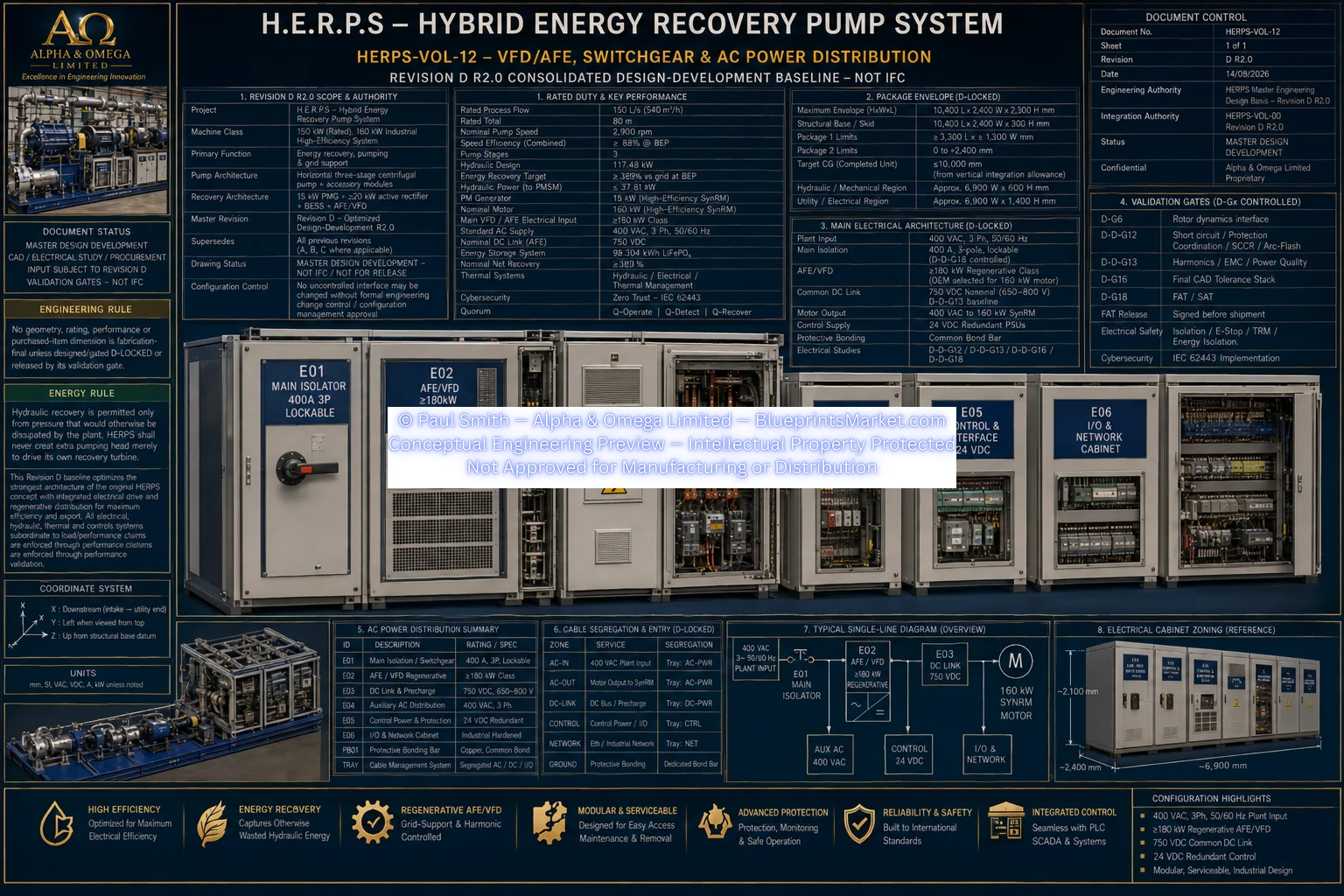
HERPS-VOL-12-VFD-AFE-SWITCHGEAR-AND-AC-POWER-DISTRIBUTION-REV-D-R2.0.webp
Engineering Document Status
Revision D R2.0 — Consolidated Design-Development — Not IFC
The HERPS engineering documentation represents advanced conceptual and design-development engineering. Final manufacturing, installation and certification require completion of the applicable engineering validation, OEM equipment selection, site-specific electrical studies, regulatory review and formal design-release processes.
Explore the Complete H.E.R.P.S Revision D Engineering System
HERPS Volume 12 forms part of the complete multi-volume Revision D engineering documentation package covering hydraulic machinery, rotating assemblies, energy recovery, electrical power conversion, thermal management, energy storage, automation, functional safety, structural integration, installation, validation, commissioning and lifecycle engineering.
View the Complete HERPS System
Contact Blueprints Market for product, licensing and engineering-documentation enquiries.