© Paul Smith — Alpha & Omega Limited — PlatformClouds.com — Conceptual Engineering Preview — Not Approved for Manufacturing
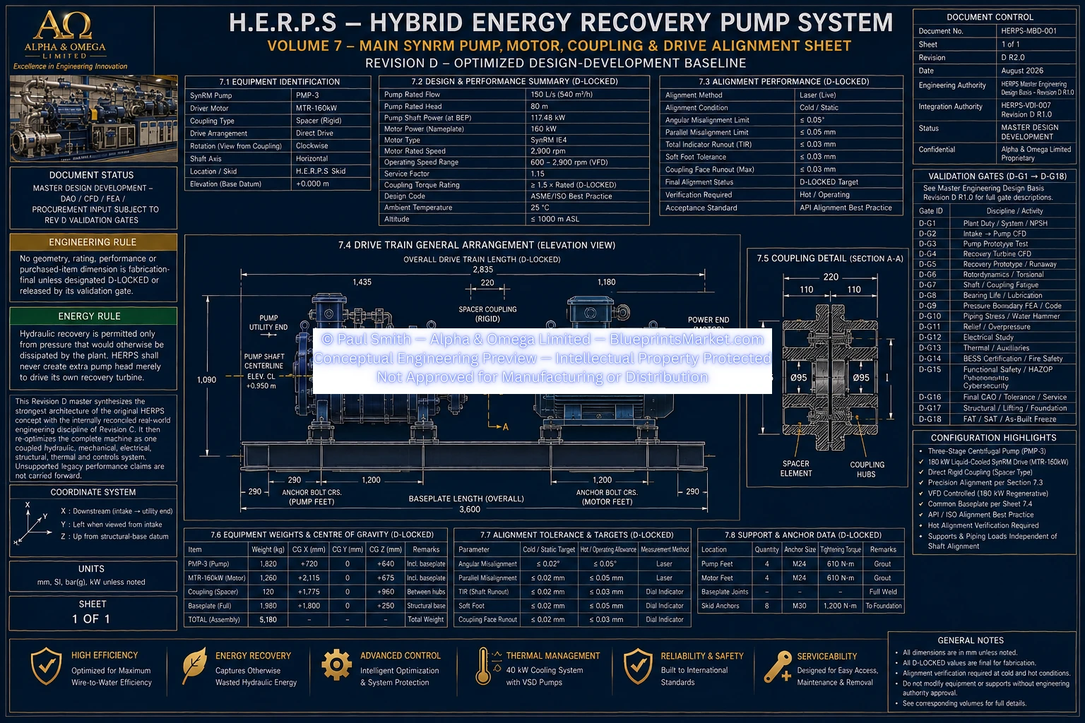
HERPS-VOL-07-MAIN-SYNRM-PUMP-MOTOR-COUPLING-AND-DRIVE-ALIGNMENT-REV-D-R2.0.webp

Revision D R2.0 — 160 kW Liquid-Cooled SynRM • Regenerative AFE/VFD • Pump-Motor Coupling • Alignment • Variable-Speed Drive
Engineering overview of the H.E.R.P.S Revision D main pump drive train, integrating the high-efficiency synchronous reluctance motor, pump-motor coupling, controlled shaft alignment, variable-speed operation, cooling, protection and regenerative electrical-drive architecture.
The H.E.R.P.S Revision D main drive system is centered on a 160 kW liquid-cooled industrial synchronous reluctance motor serving the three-stage centrifugal pump.
Revision D replaces the earlier 150 kW permanent-magnet synchronous motor baseline with the 160 kW SynRM architecture and coordinates the motor with the pump shaft, flexible coupling, alignment system, cooling circuit and regenerative AFE/VFD electrical drive.
The complete drive train is treated as an integrated mechanical, electrical and thermal system rather than as an isolated motor.
| Parameter | Revision D R2.0 Basis |
|---|---|
| Main Motor | 160 kW liquid-cooled high-efficiency industrial SynRM baseline |
| Motor Efficiency Target | ≥96.5% at H.E.R.P.S rated duty |
| Target Pump Shaft Power | Approximately 132.01 kW at the Revision D rated design basis |
| Calculated Nominal Shaft Torque | Approximately 434.7 N·m |
| Nominal Pump Speed | 2,900 rpm |
| Controlled Speed Envelope | 1,500–3,600 rpm, subject to prohibited resonant bands |
| Main AFE/VFD | ≥180 kW continuous regenerative drive class |
| Plant Electrical Interface | 400 VAC, 3-phase, 50/60 Hz |
| Common DC Link | 750 VDC nominal |
| Engineering Status | Revision D R2.0 Consolidated Design-Development — Not IFC |
The Revision D motor baseline uses a high-efficiency synchronous reluctance motor selected for variable-speed industrial pump duty.
The motor is coordinated with the H.E.R.P.S hydraulic operating point, the selected regenerative drive, thermal-management system, shaft alignment requirements, overload duty and rotordynamic operating envelope.
The coupling forms the controlled mechanical interface between the SynRM motor shaft and the H.E.R.P.S pump shaft.
Its function is to transmit the required operating torque while allowing the complete rotating train to be assembled, aligned, inspected and maintained within the Revision D machinery arrangement.
Final selected coupling geometry, hub dimensions, bore details, balancing class and vendor-specific installation requirements remain controlled by the selected OEM and applicable rotordynamic validation.
Pump-motor alignment is a controlled installation and acceptance function. Revision D requires the drive train to be aligned in coordination with the structural skid, pump mounting, motor mounting, coupling, connected piping and thermal-growth basis.
Alignment is not considered complete merely when the motor and pump are initially placed on the skid. Final connected alignment is verified after the permanent hydraulic piping and other relevant package interfaces are installed.
Revision D uses a regenerative active-front-end variable-frequency-drive architecture sized for the 160 kW SynRM motor and the required operating envelope.
The H.E.R.P.S main motor is operated through the VFD so pump speed can respond to actual process flow and pressure requirements.
The nominal operating speed is 2,900 rpm, with a controlled 1,500–3,600 rpm development envelope. Final continuous operating regions exclude any prohibited resonant bands established by the Revision D rotordynamic validation process.
Variable-speed operation is the primary normal means of hydraulic process control and reduces the need to dissipate useful pump head through unnecessary throttling.
The motor and power-electronic drive are integrated with the H.E.R.P.S thermal-management system so that operating temperature is controlled across the intended load and speed range.
Cooling performance forms part of the motor, VFD and complete-machine acceptance process. Thermal capability must remain adequate during representative load conditions and cannot be assumed solely from nominal equipment ratings.
The Revision D drive system incorporates coordinated isolation, protective bonding, drive protection, controlled precharge and discharge, torque-removal functions and interaction with the H.E.R.P.S functional safety architecture.
The motor-drive interface includes VFD-rated power cabling, protective earth and shielding provisions, controlled cable routing and segregation from instrumentation and low-level control wiring.
Final cable sizes, short-circuit ratings, breaker and fuse selections, harmonic mitigation, grounding details and protection settings are released only after the applicable Revision D electrical study and site information are complete.
The Revision D acceptance process verifies the motor and drive as part of the complete H.E.R.P.S package.
HERPS-VOL-07-MAIN-SYNRM-PUMP-MOTOR-COUPLING-AND-DRIVE-ALIGNMENT-REV-D-R2.0.webp
HERPS-VOL-07 Revision D R2.0 is the controlled design-development volume for the main pump motor, pump-motor coupling and drive alignment of the H.E.R.P.S Revision D machine.
The volume supports coordinated CAD, OEM enquiry and procurement input, rotordynamic, electrical and thermal analysis, installation planning and FAT/SAT preparation.
Final OEM dimensions, coupling details, drive settings, cable sizes, protection settings, rotordynamic prohibited bands and measured as-built values are frozen only through their applicable Revision D validation and release gates.
Master Design-Development — Not IFC — Not Approved for Manufacturing.