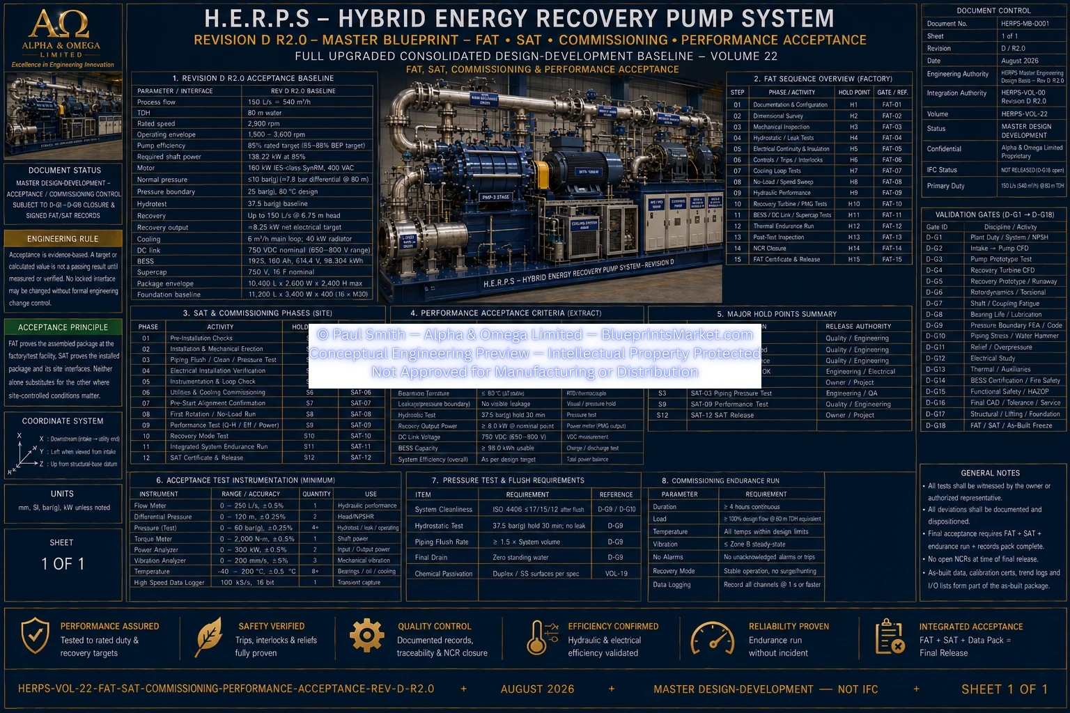
H.E.R.P.S — FAT, SAT, Commissioning & Performance Acceptance
HERPS-VOL-22 — Revision D R2.0
Hybrid Energy Recovery Pump System (H.E.R.P.S)
Revision D Acceptance & Commissioning Program
HERPS-VOL-22 defines the factory acceptance testing, site acceptance testing,
commissioning sequence, performance verification, acceptance records and
release-signature requirements for the H.E.R.P.S Hybrid Energy Recovery Pump System.
The acceptance program covers dimensional verification, hydrostatic testing,
hydraulic Q-H performance, efficiency, power, NPSHR, vibration, bearing temperature,
electrical protection, recovery-mode operation, BESS and DC systems, thermal
management, instrumentation, trips, interlocks, commissioning and signed
acceptance records.
Revision D R2.0 Acceptance Baseline
| Acceptance Parameter |
Revision D R2.0 Basis |
| Machine |
160 kW-drive-class horizontal three-stage variable-speed centrifugal industrial water pump with controlled hydraulic-energy-recovery path |
| Rated Process Flow |
150 L/s — 540 m³/h |
| Rated TDH |
80 m water |
| Rated Speed |
2,900 rpm |
| Operating Envelope |
1,500–3,600 rpm subject to released exclusion map |
| Pressure Boundary |
25 bar(g), 80 °C design baseline |
| Hydrotest |
37.5 bar(g) baseline subject to approved governing code/material factors |
| Recovery Flow |
Up to 150 L/s at 6.75 m available head |
| Nominal Recovery Output Target |
Approximately 8.25 kW net electrical at the nominal genuine recovery condition |
| Cooling |
6 m³/h nominal main loop; 40 kW radiator |
| DC Link |
750 VDC nominal; 650–800 V controlled |
| BESS |
192S, 160 Ah, 614.4 V nominal, 98.304 kWh |
| Supercapacitor |
750 V, 16 F nominal |
| Package Envelope |
10,400 × 2,600 × 2,400 mm maximum |
Evidence-Based Acceptance Philosophy
- A calculated value, CAD dimension or engineering target is not a passing result until verified by the approved test or inspection procedure.
- All acceptance instruments require traceable calibration appropriate to the measurement and tolerance.
- The test article must use the released Revision D R2.0 configuration.
- Temporary spools, bypasses, overrides, disabled trips or substitute components must be identified and dispositioned.
- Safety-critical trips and mechanical relief independence are verified without relying solely on HMI indication.
- Non-conformances must be recorded, classified, dispositioned and closed or formally accepted.
- FAT proves the assembled factory package; SAT proves the installed package and site-controlled interfaces.
Factory Acceptance Test Preconditions
- Applicable D-G1 through D-G17 engineering releases available or formally dispositioned.
- Factory assembly matches released GA, P&ID, electrical single-line, wiring schedule, cause/effect and BOM revision.
- Pressure-boundary design and relief basis approved.
- Rotor, shaft, bearing, alignment and balance records available.
- Electrical protection and settings basis loaded into the test configuration.
- BESS-certified configuration and safety instructions available.
- E-stop and hardwired safety-trip circuits complete.
- Test instrumentation calibrated with certificates available.
- Approved FAT procedure, risk assessment/JSA, isolation plan and test sheets issued.
- Blocking manufacturing NCRs closed before FAT.
FAT Sequence & Hold Points
| Step |
Factory Activity |
| FAT-01 | Document and configuration verification |
| FAT-02 | Dimensional and as-built survey |
| FAT-03 | Mechanical inspection, rotor free rotation, alignment and guards |
| FAT-04 | Hydrostatic and leak tests |
| FAT-05 | Electrical continuity, insulation, bonding and phase/drive checks |
| FAT-06 | Control I/O, permissive, trip and interlock simulation |
| FAT-07 | Cooling-loop fill, flush, flow and thermal functional checks |
| FAT-08 | No-load / low-load rotation and speed sweep |
| FAT-09 | Pump hydraulic performance and NPSHR testing |
| FAT-10 | Recovery turbine / PMG / rectifier testing |
| FAT-11 | BESS / DC-DC / supercapacitor / DC-link testing |
| FAT-12 | Integrated thermal/load endurance run |
| FAT-13 | Final trip tests and controlled shutdown |
| FAT-14 | Post-test inspection and NCR closure |
| FAT-15 | Signed FAT certificate and shipment release |
Dimensional & Physical Acceptance
| Survey Item |
Acceptance Requirement |
| Complete Envelope | ≤10,400 L × 2,600 W × 2,400 H mm |
| Structural Base | 10,400 L × 2,400 W × 300 mm deep baseline |
| Pump / Motor Shaft | Y = 0; Z = +800 mm |
| Turbine / Generator Shaft | Y = +950; Z = +850 mm |
| Main Discharge Header | Y = +850; Z = +1,300 mm |
| Main Suction | Y = 0; Z = +800 mm |
| Pump / Motor Coplanarity | ≤0.25 mm before shims |
| Base Mounting Flatness | ≤0.10 mm across each foot set |
| Final Parallel Alignment | ≤0.05 mm |
| Final Angular Alignment | ≤0.05° with approved hot-growth correction |
Mechanical, Hydrostatic & Leak Testing
- Rotor must rotate without rub, binding or abnormal resistance.
- Journal TIR acceptance ≤0.015 mm where measured by the approved method.
- Assembled rotor TIR at impeller OD ≤0.05 mm where measurable.
- Coupling and rotating guards installed before applicable operation.
- Main pressure hydrotest baseline 37.5 bar(g), subject to governing-code release.
- Zero visible pressure-boundary leakage.
- Cooling-system pressure/leak testing performed to the approved 6 bar-loop/component basis.
- High-point vents and low-point drains must function correctly.
- No permanent deformation, joint distress, gasket extrusion or instrument damage after pressure testing.
Pump Hydraulic Performance — Q-H, Efficiency & Power
Hydraulic performance testing establishes the measured pump curve using water
with documented density and temperature. Flow, suction pressure, discharge
pressure, speed, power and temperature are recorded across sufficient operating
points to establish the Q-H, efficiency and power characteristics.
- Rated point target: 150 L/s at 80 m TDH.
- Rated speed: 2,900 rpm unless an approved correction method is applied.
- Minimum, rated, maximum and sufficient intermediate curve points are measured.
- Measured power is recorded across the operating curve.
- The 160 kW motor must not overload within the approved operating envelope.
- Unstable head characteristics, severe vibration, seal distress and bearing overtemperature are unacceptable.
- Raw data, calibration information, uncertainty, corrected values and calculations are retained.
NPSHR & Cavitation Performance Testing
Measured NPSHR is established using an approved ISO/project method and correlated
with the hydraulic design. Final site NPSHA margin is based on measured performance,
not a text-only design value.
- Controlled suction-pressure reduction is performed at selected flow points.
- Head degradation, suction pressure, flow, speed, vibration, noise and cavitation evidence are recorded.
- NPSHR is established at or around the 150 L/s rated duty and other required operating points.
- If measured NPSHR is unacceptable, the hydraulic/intake/impeller design is reopened rather than masking the deficiency through controls.
Vibration, Rotordynamic & Bearing-Temperature Acceptance
- Pump vibration must remain within the approved machine-class limits.
- VT-101X/Y and VT-102X/Y provide DE and NDE vibration measurement.
- A controlled speed sweep verifies prohibited resonances and exclusion bands.
- TT-101, TT-102 and TT-103 bearing temperatures must stabilize within supplier limits.
- 95 °C high-high is a baseline ceiling or the lower supplier limit applies.
- No abnormal spectral components, rub signatures, resonance discrepancies or thermal runaway are accepted.
Motor, AFE/VFD & Electrical Protection FAT
- Protective bonding continuity verified across motor, generator, cabinets, trays and piping bonds.
- Approved insulation resistance/dielectric tests completed within OEM limits.
- Correct motor rotation and encoder/speed feedback confirmed.
- AFE/VFD operates the motor through the rated point and approved operating range.
- Installed protection settings must match the approved electrical study.
- 750 VDC nominal DC-link operation and 650–800 V controlled window verified.
- DC-link overvoltage protection baseline ≥820 VDC verified by an approved safe method.
- Loss-of-supply and emergency-stop responses verified.
Hydraulic Energy-Recovery FAT
The direct DN300 and recovery DN300 paths operate in parallel and rejoin
downstream. Testing verifies the hydraulic relationship:
Qpump = Qdirect + Qrecovery.
- Normal process operation must remain available with recovery bypassed or disabled.
- Ten adjustable guide vanes are verified over the 0–25° command range.
- FT-301 confirms recovery flow never exceeds measured pump flow.
- PT-301 and PT-302 establish actual recoverable head.
- Turbine/PMG power is mapped against flow, head and speed.
- Approximately 8.25 kW net electrical is a target only where approximately 6.75 m of genuinely otherwise-wasted head exists at the relevant flow.
- The direct path must preserve required process flow following a turbine trip.
- No operating mode may increase pump head solely to manufacture recoverable power.
BESS, Bidirectional DC/DC & High-Voltage Safety FAT
| Parameter |
Acceptance Basis |
| Pack | 192S, 160 Ah, 614.4 VDC nominal, 98.304 kWh |
| Module Baseline | 12 × 16S modules |
| Continuous DC/DC Power | Nominally 150 kW subject to certified limits |
| Peak Power | 200 kW ≤30 s only where supplier/BMS certification permits |
| SOC Window | 10–90% baseline unless approved supplier limits differ |
| Safety | BMS, IMD, contactors, precharge, HVIL, alarms and emergency isolation verified |
Supercapacitor & DC-Link Transient FAT
- Supercapacitor bank: 750 VDC, 16 F nominal.
- Theoretical stored-energy reference: 1.25 kWh at 750 V.
- Approximately 0.694 kWh usable reference from 750 V to 500 V before losses.
- Bidirectional converter baseline: ≥250 kW short-duration.
- Regenerative capture must occur without DC-link overvoltage or converter instability.
- Overcurrent, overtemperature, isolation, precharge/discharge and residual-voltage indication are verified.
Thermal-Management FAT
| Test Item |
Acceptance |
| Main Cooling Flow | 6 m³/h nominal |
| Low-Flow Alarm | <4.5 m³/h baseline |
| Low-Flow Trip | <3.5 m³/h after validated delay |
| Radiator | 40 kW nameplate minimum at project ambient after corrections |
| PHE | 40 kW baseline |
| Reservoir | 80 L |
| Expansion Tank | 50 L |
| Motor Coolant Inlet | 25–35 °C target where test conditions permit |
| Coolant High Alarm | 45 °C baseline |
| Coolant High-High Trip | 55 °C or lower OEM limit |
Instrumentation & I/O Verification
- Pressure and differential-pressure transmitter zero/span and PLC scaling verified.
- FT-101 and FT-301 flow signal direction, scaling and recovery mass-balance logic verified.
- Pump and turbine speed instrumentation verified.
- Four vibration channels verified through alarm/trip routing.
- Three Pt100 bearing-temperature channels verified.
- Cooling flow and reservoir-level alarm/trip functions verified.
- DC voltage/current transducers verified against reference measurement.
- BMS SOC/SOH and critical-fault communication verified.
- Two opposite-side E-stop stations and dual-channel hardwired loop verified.
Trip, Interlock & Cause-and-Effect Acceptance
| Condition |
Revision D Baseline |
| Pump Overspeed | >3,750 rpm baseline — immediate VFD torque inhibit |
| Turbine Overspeed | Released hardware trip; preliminary controlled ceiling subject to final release |
| Discharge High-High | ≥11 bar(g) baseline |
| Bearing High-High | ≥95 °C or lower supplier limit |
| Vibration High-High | 7.1 mm/s RMS baseline pending final machine-class setting |
| Cooling Low Flow | <3.5 m³/h sustained |
| DC-Link Overvoltage | ≥820 VDC baseline |
| BESS Insulation Fault | Open BESS contactors; preserve grid pump operation where safe |
Every required cause and effect must be physically observed, timed and recorded.
PLC or HMI indication alone is insufficient for hardwired safety functions.
Integrated FAT Endurance Run
- Warm-up until oil, coolant and bearing-temperature trends stabilize.
- Sustain rated 150 L/s at 80 m where the test facility permits.
- Record flow, head, speed, power, vibration, temperatures, seal leakage and cooling.
- Exercise manual, automatic and recovery/direct-path transitions.
- Exercise approved BESS peak-shaving/ride-through and supercapacitor transient functions.
- Demonstrate recovery-mode fallback to the direct hydraulic path.
- Verify normal stop, standby auxiliaries, restart permissives and restart sequence.
- No unresolved trip, leak, overheating, abnormal vibration, control oscillation or hardware fault is accepted.
Site Acceptance Test Preconditions
- Site-approved foundation, anchors and grout complete and surveyed.
- Electrical supply, process piping, drainage, ventilation/cooling and communications available.
- Actual site short-circuit and protection settings installed.
- Plant NPSHA and downstream pressure profile confirmed.
- Skid anchored/grouted with independently supported piping and acceptable nozzle strain.
- Final piping-connected alignment completed with hot-growth compensation.
- BESS fire/electrical/site approvals and emergency-response interfaces complete.
- LOTO, guarding, relief discharge, E-stops and safe access complete.
- Approved commissioning procedure, responsibilities and abort criteria issued.
Site Mechanical & Electrical Acceptance
- Foundation baseline: 11,200 × 3,400 × 400 mm development basis or approved site-engineered replacement.
- 16 × M30 concept anchor positions or approved site structural design.
- 25–50 mm non-shrink machinery grout where required.
- DN350 suction, DN300 discharge/direct and DN300 recovery piping installed without unacceptable nozzle strain.
- 400 VAC, 3-phase, 50/60 Hz supply within approved limits.
- Skid, motor, PMG, cabinets, trays and piping bonds connected to the site protective earthing system.
- Field I/O loops checked end-to-end after shipping and reconnection.
- BESS/DC service disconnects, precharge, IMD, contactors, HVAC and emergency isolation verified on site.
Controlled Commissioning Sequence
- Verify permits, LOTO boundaries and signed mechanical/electrical completion.
- Flood and vent the pump/suction system as required and verify seal-flush and cooling availability.
- Place the recovery path in safe bypass/direct mode.
- Energize control power and verify PLC/HMI, E-stops, BMS, drives, instrumentation and communications.
- Energize auxiliaries and establish cooling flow.
- Confirm final motor rotation.
- Start the pump at controlled low speed without deadhead or hydraulic shock.
- Increase speed and load in defined steps while recording hydraulic, vibration, thermal and electrical data.
- Establish stable process duty and compare against FAT performance.
- Enable and tune automatic flow/pressure control within approved limits.
- Introduce recovery gradually only when genuine recoverable downstream pressure is available.
- Verify Qpump = Qdirect + Qrecovery without compromising process duty.
- Exercise normal stop, controlled trip, emergency stop and restart.
- Complete the required endurance period and close the commissioning punch list.
Site Performance Acceptance
- Demonstrate site operation consistent with the FAT pump curve.
- Verify rated 150 L/s at 80 m where installed plant duty permits direct verification.
- Confirm measured site NPSHA margin over measured NPSHR.
- Verify vibration limits without installation-induced structural or piping resonance.
- Verify stable bearing temperatures.
- Confirm motor/VFD current, power and DC-link behavior.
- Accept recovery power only against measured recovery flow and head.
- Verify stable cooling at actual ambient and altitude.
- Verify automatic flow/pressure/recovery coordination and direct-path fallback.
- Complete the project endurance period without unresolved trips, thermal drift or degradation.
Performance Calculation & Data-Reduction Rules
Hydraulic Power: Ph = ρgQH
Revision D rated hydraulic-power reference:
117.48 kW at 998 kg/m³, 0.15 m³/s and 80 m.
Pump efficiency is determined from measured hydraulic power divided by
measured shaft power. Where electrical input is used, validated motor and
drive losses must be explicitly accounted for.
Recovery Hydraulic Power: Prec,h = ρgQrecHrec
Nominal Revision D recovery hydraulic-power reference:
9.91 kW at 150 L/s and 6.75 m.
Net recovered electrical power is measured at the defined electrical boundary.
Recovery energy must not be credited twice and must not be represented as
self-sustaining energy.
Acceptance Records & Traceability
- FAT-1401: Approved procedures, test sheets, calibration, raw/processed data, witness signatures, NCRs and FAT certificate.
- SAT Record: Site preconditions, installation survey, loop checks, performance results, trip tests and SAT certificate.
- COM-2201: Commissioning log with operating mode, setpoints, changes, observations, alarms, trips and corrective actions.
- PER-2202: Performance report covering Q-H, efficiency, power, NPSHR, recovery, vibration, thermal results and uncertainty.
- ASB-1501: Final measured coordinates, alignment, vendor part numbers, serial numbers and as-built deviations.
- PLC, HMI, VFD, BMS, EMS and converter software/configuration archives.
- Calibration certificates and instrument traceability.
- Pressure, NDE, material, vendor, BESS and electrical conformity certificates.
- Punch-list and NCR closure records.
Final Acceptance & Release
Final HERPS acceptance requires completion of the applicable factory and
site tests, closure or formal disposition of non-conformances, approved
as-built records, commissioning records, performance results and required
release signatures.
Shipment is released only after mandatory FAT hold points and documentation
are complete. Final operating acceptance additionally requires successful
SAT, commissioning and performance verification under the actual approved
site conditions.
Revision D Engineering Status
HERPS-VOL-22 Revision D R2.0 is the master design-development acceptance
and commissioning control volume. Final acceptance remains subject to
closure of the applicable D-G1 through D-G18 engineering gates and the
approved FAT, SAT, commissioning and as-built records.
Validation-controlled values, supplier limits, site-specific protection
settings, measured NPSHR, final machine-class vibration limits and other
controlled acceptance parameters are not replaced by unverified design
targets.
Explore the Complete H.E.R.P.S Revision D System
FAT, SAT, Commissioning & Performance Acceptance forms part of the complete
H.E.R.P.S Revision D multi-volume conceptual engineering blueprint system.
View the Complete HERPS System
Contact Blueprints Market for product,
licensing and engineering-package enquiries.
© Paul Smith — Alpha & Omega Limited — PlatformClouds.com — Conceptual Engineering Preview — Not Approved for Manufacturing
HERPS-VOL-22-FAT-SAT-COMMISSIONING-PERFORMANCE-ACCEPTANCE-REV-D-R2.0.webp
